Download
1 / 1
10 likes | 169 Views
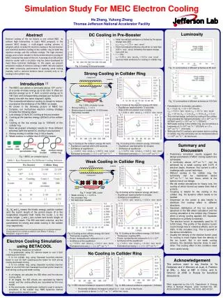
Simulation Study For MEIC Electron Cooling He Zhang, Yuhong Zhang Thomas Jefferson National Accelerator Facility. Cooling section. ion bunch. solenoid. ion bunch. electron bunch. electron bunch. solenoid. Cooling section. Fast kicker. Fast kicker. Fast kicker. circulator ring.

E N D
Simulation Study For MEIC Electron Cooling He Zhang, Yuhong Zhang Thomas Jefferson National Accelerator Facility Cooling section ion bunch solenoid ion bunch electron bunch electron bunch solenoid Cooling section Fast kicker Fast kicker Fast kicker circulator ring Fast kicker circulator ring Luminosity dump SRF Linac injector Abstract Electron cooling of the ion beams is one critical R&D to achieve high luminosities in JLab’s MEIC proposal. In the present MEIC design, a multi-staged cooling scheme is adapted, which includes DC electron cooling in the pre-booster and bunched electron cooling in the collider ring at both the injection energy and the collision energy. The high electron energy and current needed in the bunched electron cooling of MEIC is beyond the-state-of the-art. A concept of an ERL driven electron cooler with a circulator ring has been developed to meet these technical challenges. In this paper, we present simulation studies of electron cooling in MEIC. We also explore the MEIC luminosity performance if applying weak cooling (namely, with a reduced electron beam current) only or no cooling in the collider ring. DC Cooling in Pre-Booster dump injector SRF Linac • Initial normalized emittance is limited by the space charge tune shift. • Final normalized emittance should be no less than 0.55 , limited by the space charge tune shift too. • , • used as initial emittance for cooling in collider ring. Fig. 2 Cooling in the pre-booster Fig. 13 Luminosities of different schemes at 60 GeV Strong Cooling in Collider Ring • Introduction[1] • The MEIC can deliver a luminosity above 1034 cm-2s-1 at a center-of-mass energy up to 65 GeV. It offers an electron energy up to 11 GeV, a proton energy up to 100 GeV, and corresponding energies per nucleon for heavy ions with the same magnetic rigidity. • The conventional electron cooling is chosen to reduce or preserve the emittance of the MEIC ion beam. • As shown in the following picture of MEIC Ion Complex, our multi-phase electron cooling strategy includes the following steps: • Low energy (3 GeV) DC cooling at the pre-booster • Cooling at the injection energy (25GeV) of the collider ring • Cooling at the top energy (up to 100GeV) of the collider ring • Here we present simulation results for three different schemes (with the same DC cooling in pre-booster) • Strong cooling in collider ring (1.5A e- beam) • Weak cooling in collider ring (0.375 A e-beam) • No cooling in collider ring Fig. 14 Luminosities of different schemes at 100 GeV • Fig. 4 Cooler at the injection energy (25 GeV) • Equilibrium reached within 70 seconds • Stop at 40 s to prevent over cooling • Fig. 3 ERL circulator cooler • Strong cooling, • Electron bunch reused for 10-100 times • Fast kicker needed • Parameters for luminosity calculation: • , • , • , ,, • The nominal design (with strong cooling in the collider ring) provides the highest luminosity. (60GeV) and (100GeV) • With weak cooling in the collider ring, we can achieve a luminosity of (60 GeV) or (100 GeV) • With only the DC cooling in pre-booster and no cooling in collider ring, the luminosity can be maintained above for two hours. • Summary and Discussion • Preliminary simulation results suggest the design parameters of MEIC cooling system are achievable. • A luminosity above can be achieved by a weak cooling with 0.375 A electron beam. However, this current is still a challenge with current technique. • Without cooling in the collider ring, the luminosity can be maintained above for two hours, which is the bottom line of our design. • We did similar simulations for heavy ions, the cooling of which turned out easier than that of protons. • Coupling is helpful for the cooling in the collider ring. It’s dynamic effect needs to be studied. • Dispersion at the cooler is also helpful to distribute the cooling effect in different directions. • Gaussian distribution of the ion bunch is assumed in the IBS effect calculation and the cooling simulation in the collider ring. However when a strong cooling applied, the Gaussian distribution is unlikely to maintain. • The electron bunch is repeatedly used for 10 to100 times. The profile of the electron bunch could change due to collective effects, such as CSR, in the circulator ring. This is ignored in the above simulations. • Usually the density of the electron bunch used for cooling is much higher than the density of the ion bunch. But in our weak cooling scheme, the densities become close to each other. The cooling effect in this condition need more careful study. • Fig. 5 Cooling at the collision energy (60 GeV) • Equilibrium reached within 200 seconds • Emittance at equilibrium • Estimated luminosity • Fig. 6 Cooling at the collision energy (100 GeV) • Equilibrium reached within 30 minutes • Emittance at equilibrium • Estimated luminosity Fig. 1 MEIC ion complex layout Weak Cooling in Collider Ring • Fig. 8 Cooling at the injection energy (25 GeV) • Equilibrium reached within 4 minutes • Emittance at equilibrium • Fig. 7 “weak” ERL cooler • Weak cooling, • No circulator ring • No fast kicker needed Ep, Np and lp means the kinetic energy, particle number and the bunch length of the proton beam. B is the longitudinal magnetic field inside the cooler. lc is the cooler length. Ie and le are current and bunch length of the electron beam. The fifth and sixth columns are the parameters for strong and weak cooling in the collider ring respectively. [1] Science requirements and conceptual design for a polarized medium energy electron-ion collider at Jefferson Lab, Editors: Y. Zhang, J. Bisognano, August 10, 2012 • Fig. 10 Cooling at the collision energy (100 GeV) • Transverse coupling 80% • Proton number/bunch reduced to • Emittance at the equilibrium • Estimated luminosity • Fig. 9 Cooling at the collision energy (60 GeV) • Transverse coupling 70% • Proton number/bunch reduced to • Emittance at the equilibrium • Estimated luminosity • Electron Cooling Simulation using BETACOOL • The following stages are simulated: • 1. In prebooster, using DC electron beam to cool 3 GeV coasting proton beam • 2. In ion collider ring, using Gaussian bunched electron beam to cool 25 GeV coasting proton beam for both strong cooling and weak cooling • 3. In ion collider ring, using Gaussian bunched electron beam to cool 60/100 GeV Gaussian bunched proton beam for both strong cooling and weak cooling • In all stages, we calculate the IBS effect and the electron cooling effect. • In all stages, the IBS effects are calculated by Martini model, and the cooling effects are calculated by thin lens model. • In the pre-booster, model beam method is used in dynamic simulation. In the collider ring, RMS dynamics method (single particle model) is used. No Cooling in Collider Ring Acknowledgement The authors want to say thanks to YaDerbenev and V. Morozov at JLab, A. Fedotov at BNL, L. Mao at IMP in China, and A. Smirnov at JINR in Russia for beneficial discussions. Work supported by the U.S. Department of Energy, Office of Nuclear Physics, under Contract No. DE-AC05-06OR23177 and No. DE-AC02 -06CH11357. Fig. 11 IBS induced emittance expansion (60GeV) Fig. 12 IBS induced emittance expansion (100GeV) • Horizontal emittance increases to about in two hours • Luminosity is above within two hours