Download

1 / 41
410 likes | 538 Views
This study by Peter Clark and associates at the Met Office investigates high-resolution modeling of extratropical cyclone dynamics, focusing on the role of ice evaporation on frontal systems. Utilizing the Unified Model at resolutions down to ~1 km, the research examines convection microphysics and validation through radar and dropsonde data, particularly in the context of the FASTEX event. Findings indicate that high-resolution simulations improve representation of smaller scales but have limited impact on larger-scale dynamics, emphasizing the need for accurate diabatic heating representation and understanding uncertainties in microphysical parameterization.

E N D
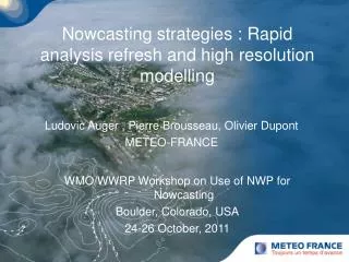
Modelling the high resolution structure of frontal rainbands Peter Clark, Richard Forbes, Humphrey Lean Met Office (JCMM) Talk Outline • Resolution dependence of extra-tropical cyclone modelling • The impact of ice evaporation on frontal dynamics Research at the Joint Centre for Mesoscale Meteorology • “Stormscale” NWP: the Unified Model at ~1km resolution • Convection / Microphysics / Validation using radar / Data assimilation
FASTEX IOP 16 Cyclone12Z 17/02/1997 Cloud Head Convection
IOP 16 Radar and Dropsonde data C130 Run 5 C130 Run 1 Figures show C130 w, IWC, wind P3 Radar reflectivity Roberts and Forbes (2002, Atmos. Sci. Lett.)
FASTEX IOP 16 Cyclone Emerging multiple cloud heads 06Z 09Z 09Z 12Z
Non-Hydrostatic Simulations • 60km global • Horizontal Resolutions: 24km, 12km, 4km, 2km LAMs, ~300x250 grid points • Vertical Resolutions: 2km with 45, 90 and 135 levels i.e. 400m, 200m and 130m mid-trop. layer spacing approx. • 12km ‘AC’ scheme analysis valid at 0Z, 9 hour forecast
FASTEX IOP 16 Cyclone Simulation 12 km 4 km 2 km
800 hPa Vertical Velocity as a function of resolution ; FASTEX IOP 16 Cyclone 60 km -0.15 -0.75 m/s 12 km 24 km 4 km 2 km
Power Spectrum of vertical velocity Same Region at 60, 24, 12, 4, 2 km grid Excluding frontal region Possible aliasing from fronts (not present in 2 km run)
Frontal Collapse to gridscale 12 km 4 km 2 km
Ratio of Vertical Velocity Power Spectrum to Spectrum at 2 kmNormalized By Grid Scale dx/5 dx/2
800 hPa Vertical Velocity as a function of resolution ; FASTEX IOP 16 Cyclone 09Z (T+9) 12/02/1997 60 km -0.15 -0.75 m/s 12 km 24 km Cross Section 1 4 km 2 km
Cross Frontal Velocity as a function of resolution ; FASTEX IOP 16 Cyclone m/s -15 -10 0.0 5 60 km 450 km 0 hPa 24 km 12 km 1000 hPa 4 km 2 km
Slantwise instability of front: 2km Simulations 400 hPa 45 Levels ~ 400 m 950 hPa 200 km 90 Levels ~ 200 m ~75 hPa Slope: 1/20-1/30 135 Levels ~ 130 m
Slantwise instability of front: 2km 90 level simulations Reference No sublimation cooling
800 hPa Vertical Velocity as a function of resolution ; FASTEX IOP 16 Cyclone Averaged to 60 km grid 60 km m/s -0.1 0.3 12 km 24 km 4 km 2 km
Vertical Velocity at 800 hPa 24 km L45 12 km L45 4 km L45 2 km L45 2 km L90 2 km L135
Vertical Velocity at 800 hPaaveraged to 60 km 24 km L45 12 km L45 4 km L45 2 km L45 2 km L90 2 km L135
Vertical VelocityCross section 24 km L45 12 km L45 4 km L45 2 km L45 2 km L90 2 km L135
Vertical Velocity Averaged to 60 km 24 km L45 12 km L45 4 km L45 2 km L45 2 km L90 2 km L135
Dry PV at 800 hPa 24 km L45 12 km L45 4 km L45 2 km L45 2 km L90 2 km L135
PV Cross Section 24 km L45 12 km L45 4 km L45 2 km L45 2 km L90 2 km L135 -3x10⁻⁶ 3x10⁻⁶
PV Cross Section (120 km blowup) 24 km L45 12 km L45 4 km L45 2 km L45 2 km L90 2 km L135
PV Cross SectionAveraged to 60 km 24 km L45 12 km L45 4 km L45 2 km L45 2 km L90 2 km L135 0 3x10⁻⁶
PV Generation - Ice Fallout Saturated Ascent + Saturated Descent • On the larger scale, symmetric dipole/tripole anomalies cancel each other out. • Monopole dominates far-field response. • Dipole/tripole component of a PV anomaly has only a weak influence on the far field. -
Conclusions • Model properly represents scales greater than about 5 gridlengths • Probably some frontal aliasing at resolutions of 4km+ • Over a short forecast, high resolution simulation has only a small impact on larger scales - greater near surface fronts than in slantwise ascent • High resolution has little net impact on overall diabatic heating and on PV generation, i.e. slantwise overturning is not a strong net generator (saturated descent) • This may be why climate models work (at all!)
Impact of evaporative cooling on frontal dynamics • Cooling due to rain/snow evaporation significantly enhances frontal downdraughts • A number of papers have shown the importance of downdraughts in convective systems • Observations of strong narrow frontal downdraughts: Thorpe and Clough (1991), Browning et al. (1997) • 2D semi-geostrophic models of frontogenesis: Huang and Emanuel (1991) , Parker and Thorpe (1995) • 3D idealised front in the Met Office Unified Model (UM) • FASTEX frontal cyclone case studies using the UM: Forbes and Clark (2003, submitted to QJRMS) • For high resolution forecasting, NWP models require the correct distribution of diabatic heating and evaporative cooling. • Main surface “weather” impacts: Distribution of precipitation, wind gusts
Hypotheses • Ice evaporation is rapid in the subsaturated zone beneath a frontal surface leading to intense cooling in a shallow layer with a significant local dynamical impact. • The Unified Model does not represent the profile of evaporative cooling accurately, resulting in an incorrect dynamical response. • The UM can be improved by varying microphysical parameters within their bounds of uncertainty. Method • Evaluate the model against observations. • Understand the uncertainty in the formulation of microphysics parametrizations. • Determine the sensitivity of the moisture/dynamical fields to these uncertainties. • Predict parameter changes to give a closer fit to the observations.
Idealised Front Cloud Ice (g/kg) Vertical Wind (m/s) Diabatic Heating Rate (K/hr) Reference forecast Downdraught is significantly weaker when there is no ice evaporative cooling
FASTEX IOP16:Dynamical impact of evaporative cooling Plan view of vertical velocity at 800hPa with and without ice evaporative cooling Evaporative cooling leads to enhanced descent beneath the frontal cloud band and enhanced ascent in the frontal updraught
Does the model have the correct characteristics in the evaporation cooling zone beneath frontal updraughts ? • Few observations of downdraughts, so use proxy data. The important parameters are the vertical ice flux and the depth scale of the cooling. Can derive ice water content and evaporation depths from radar observations. • Perform statistical comparison between model and observations (1 year of data). • Timeseries from operational Unified Model forecasts Includes mixed-phase microphysics parametrization (Wilson and Ballard, 1999) • Timeseries of radar reflectivity data from the vertically pointing 94GHz cloud radar based at Chilbolton. Convert to ice water content and average to model resolution. • Algorithm extracts vertical profiles which contain ice evaporation beneath stratiform cloud.
Observations of Evaporation 94GHz Radar Derived Ice Water Content (below 0degC) Radar data provided by Robin Hogan (Reading Univ.) and RCRU (RAL) 02 Apr 2000 11 Dec 1999
Model/Obs Comparison Probability of ice evaporative depth scale from 1 year of data Evaporation depth scale cumulative probability from the operational Unified Model and the radar data averaged to 12km Radar averaged to 12km Operational model 12km resolution
Model/Obs Comparison Average ice evaporative depth scale from the Chilbolton 94 GHz cloud radar and the operational UM for 20 separate days in Oct, Nov, Dec 1999.
Model/Obs Comparison Probability of ice water content for the model and radar
Reasons for Model/Obs Differences • What are the reasons for the difference between the model and the observed depth scales ? • Hypotheses: • Inadequate vertical resolution (model layers are 500-750m) • Too much ice • Relative humidity forcing in the model subsaturated zone is too moist • Parametrized ice particle evaporation rate is too low • Parametrized ice particle terminal fall speed is too high
Microphysics Parametrization • Uncertainty in microphysical parameters • Various sources of uncertainty in microphysics parametrization schemes due to: • insufficient knowledge of the real world • simplification of the processes in the parametrization. • The ice evaporation rate and ice terminal fall speed parametrizations in the model could have a bias of a factor of 2. • Sensitivity of forecasts to parameter uncertainty • Determined the sensitivity of the model to ice evaporation rate and fall speed variations within the bounds of uncertainty (analytical, 1D evaporation model, 3D frontal cyclone forecasts) • Increasing ice evaporation rate -> stronger narrower downdraughts • Decreasing ice fall speed -> stronger narrower downdraughts, higher ice content
FASTEX IOP 16: Sensitivity Sensitivity of the model to changes that affect ice sublimation • Increasing the ice evaporation rate increases frontal development • Increasing ice terminal fall speed decreases frontal development
IOP 16 Sensitivity Forecasts:Surface precipitation Increasing ice fall speed Increasing dep/sublim rate
Summary of the Model Evaluation • Model Errors • Ice evaporation depths are too deep (by a factor of 2-3) • Ice water contents are too low (by up to a factor of 2) (?) • Suggested changes: • decrease ice fall speed (consistent with observed ice fallspeeds) • increase ice evaporation rate (consistent with ventilation assumption) • increase vertical resolution to at least 250m in mid-troposphere • Predicted Impacts • Higher ice water content and shallower, stronger frontal downdraughts.
FASTEX IOP 16: Validation Comparison of the model ice evaporative depth scales with 94GHz radar observation statistics Average depth scale Reference:1260 m Modified: 780 m Obs: 640 m (=160m)
Conclusions • Ice evaporation is rapid in the subsaturated zone beneath a frontal surface leading to intense cooling in a shallow layer. • Evaporation depth scale < 1km beneath stratiform frontal cloud • Average cooling rate of 1 K/hr. • The Unified Model does not represent the profile of evaporative cooling accurately, resulting in an incorrect dynamical response. • UM underestimates the amount of ice and overestimates the evaporative depth scales • This leads to a significant underestimate in the cooling and strength of frontal circulations. • Due to poor vertical resolution, weak ice evaporation rate, high fall speed and moist bias. • The UM can be improved by varying microphysical parameters within their bounds of uncertainty. • Many uncertainties in the microphysics of complex irregular ice particles and in microphysics parametrization formulation. • Estimate an uncertainty of up to a factor of two in the fall speed and evaporation rate. • Modifiying these two parameters improves the model fit with observations.