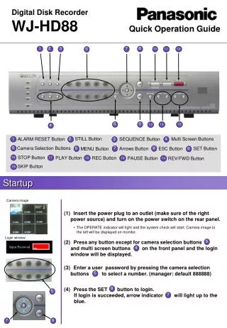
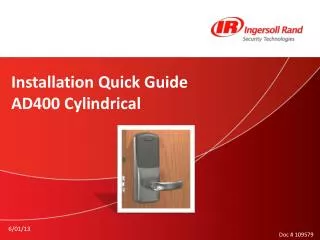
Quick Installation Guide for AD400 Cylindrical Lock
Follow this detailed quick guide to install the AD400 cylindrical lock. Begin by installing the door position switch and latch. Next, set up the clutch assembly and align the spindle based on the key cylinder type. Install the key cylinder and lever, securing the assembly properly. Step through attaching the corner posts and ensuring all components, including the anti-rotation plate and lock body, are in place. Finally, connect the necessary wiring, secure the reader, and install the batteries. Enjoy enhanced security with your new lock!

Quick Installation Guide for AD400 Cylindrical Lock
E N D
Presentation Transcript
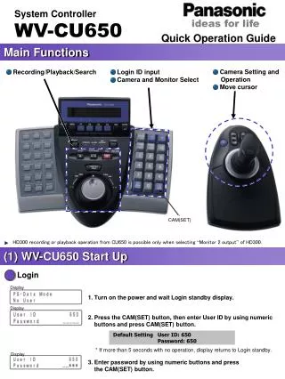
Installation Quick GuideAD400 Cylindrical 6/01/13 Doc # 109579
Step 1: Install Door Position Switch Step 2: Install Latch
Step 3: Install Clutch Assembly • Remove cover plate and insert from outside • Replace cover plate Before proceeding, verify the knob stop pin faces the edge of the door, IF NOT, re-handing is required
Step 4: Align spindle assembly based upon key cylinder type Key in Lever Cylinder InterchangeableCore Cylinder Align horizontally as shown Turn clockwise until cam stops
Step 5: Insert Key Cylinder and Lever • For locks with key in lever cylinders, place cylinder in lever • For locks with interchangeable cores, install the lever first, then insert cylinder • Insert key and turn 90 degrees to the right • Push in the knob stop pin and press lever on • Verify you can turn and remove key
Step 6: Attach the four corner posts Step 7: Make sure triangles are aligned, insert spindle beveled side up IMPORTANT! Verify both triangles are aligned
Step 8: Pull cable thru door as you place the lock body on the door Step 9: Attached anti-rotation plate with two long beveled screws Step 10: Insert the two small screws
Step 11: Attach inside lever to interior housing Step 12: Place spring on spindle and insert spindle beveled side up
Step 12: Feed wires thru lock body as you place lock body in placeStep 13: Secure lock body in place with four screws (into the four posts on the exterior housing) Step 14: Verify both the inside lever and the mechanical key retract the latch
Step 15: Connect ribbon cable. Make sure the RED wire is on the leftStep 16: Trim and connect door position switch wires • Step 17: Carefully slide out the clear tab from under coin cell battery
You’re Ready to Install the Reader Step 18: Verify the gasket is properly seated Step 19: Press reader in place Step 20: Secure reader with two long screws Do not over tighten
Step 21: Apply the reflectorStep 22: Connect wireless communication moduleStep 23: Install back cover Step 24: Install batteries and cover plate