Download
1 / 26
260 likes | 484 Views
Enhanced Hot Water Drill. System Overview Jeff Cherwinka. LBNL Collaboration Meeting March 21 st 2005. Talk Summay. Review Drill System Requirements Design Strategy Hydraulics Summary Review Seasonal Equipment Site (SES) Thermal Plant Subsystems Heaters

E N D
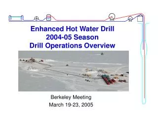
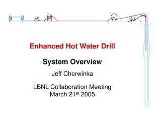
Enhanced Hot Water Drill System Overview Jeff Cherwinka LBNL Collaboration MeetingMarch 21st 2005
Talk Summay Jeff Cherwinka • Review Drill System Requirements • Design Strategy • Hydraulics Summary • Review Seasonal Equipment Site (SES) • Thermal Plant Subsystems • Heaters • Review Tower Operations Site (TOS) • Logistics and Schedule
System Overview Jeff Cherwinka • System Requirements • Drill Holes • 2,450 m (8038 ft) deep • 45 cm (17.7 in) diameter after 30 hours -> 60 cm (24 in) • Straight to within 15 m (50 ft) of vertical • Make water (Rodriguez Well) • 16,000 gal/hole for volume replacement • 6,000 gal/hole for firn drill loss • 2,000 gal/hole for IceTop • Time & Talent • Start up - 21 days with 5 people for each of 3 shifts • 84 hrs per hole with 5 people per shift -> 30 hrs deep drill • Shut down – 10 days with 5 people per shift • Fuel 115,200 gal per 16 hole season (7200 gal/hole)
System Overview Jeff Cherwinka • System Requirements (continued) • Automatic • Computer controller deep drilling mode (future) • Manual mode with control loops (present) • Safe • Tested • Logistic compatibility • Weight < 24,000 pound (10,884 kg) • Size < 8 ft (2.44 m) high, 8 ft wide, 34 ft (10.36 m) long • Fork lift 8,000 lb, Crane 30,000 lb, Tow 100,000 lb • Environmental compatibility • Operation: –45 to +38 C, rain or shine, 0 to 3,700 m • Storage: -80 to +40 C with some tagged exceptions
System Overview Jeff Cherwinka • Design Strategy • Leverage Amanda Experience • Use the same equipment where it worked • Scale up system 100 GPM->200 GPM • People with experience • Major Improvements • One “piece” drill hose – big hose reel • Automated control • Two drilling structures • Modular Design • MDS – Modular Drilling Structures • Use identical equipment where possible • Multiple smaller units • Fuel Efficiency is a design driver
System Overview Jeff Cherwinka • Hydraulics Summary • Flow – 200 GPM supply, 192 GPM return • 8 GPM makeup on average • Pressure – 950 psi at pump outlet (800 psi actual) • 10,500 feet of 2.5 in ID hose at 0.08 psi per foot • 3600 psi at bottom of hole • Temperature – 190 F (88 C) supply, 35 F (2 C) return • Power – 4.5 MW
Subsystem Overview Jeff Cherwinka • RWS – Rod Well Subsystem • Maintain water level of Tank 1 • 8 gpm average while drilling • Control flow rates to and from the Rod well • Maintain temperature of Tank 1 • Water returns from hole just above freezing • Control valves and heater firing • Equipment • Hose reel for 1-1/2 inch supply and return rod well hose • 10 Stinger heaters receive cold water from tank 1 or the rod well return, and deliver hot water to tank 1 or the rod well supply • 2 Vane Pumps (5-70 GPM@150 psi) supply water to stingers and generator heat recovery • 3 Unico drives (10 Hp) for vane pumps and rod well pump • 1 Unico drive (3 Hp) for reel motor
Subsystem Overview Jeff Cherwinka • Tank 1 • 10,000 gallon water storage, 50 F (10 C) • Level and Temp stability secondary to Tank 2 • Equipment • Two 100 GPM transfer pumps (supply to Tank2) • Return hose from Hole • Supply & Return to RWS • Return from Generator also routed to tank 2 • Tank 2 • 10,000 gallon water storage, 70 F (21 C) • Stable source of water for main loop • Equipment • 2 supply hoses from Tank 1 • Supply & Return from PHS • 4 Charge pumps with supply hoses to HPP
Subsystem Overview Jeff Cherwinka • PHS – PreHeat Subsystem • Maintain water level of Tank 2 • Control flow rates from Tank 1 using transfer pumps • Maintain temperature of Tank 2 • Control valves and heater firing • Equipment • 4 Model 75 heaters (3.50 GPH->420,000 BTU/hr) with condensate collection system • 7 Stinger heaters (2.0 GPH->220,000 BTU/hr) • 2 Vane pumps (5-70 GPM@150 psi) supply water to stingers and model 75s • 2 Unico drives (10 Hp) for vane pumps • 2 Unico drives (3 Hp) for for transfer pumps • 2 Electric water heaters (30 kW) to level generator load
Subsystem Overview Jeff Cherwinka • HPP – High Pressure Pumps • Pressurize 200 GPM of cold water to 950 psi • Equipment • High Pressure Pumps: 4 positive displacement pumps capable of 35-65 gpm @1600 psi (50 gpm @ 950 psi) • 4 Unico Drives (50 Hp) for High Pressure Pumps • 4 Unico Drives (3 Hp) for Charge Pumps • Supply manifold to combine and instrument flow to MHPs • Return manifold combines MHP return and supply to drill
Subsystem Overview Jeff Cherwinka • MHP – Main Heating Plant (MHP1, MHP2, MHP3, MHP4) • Heat 50 GPM from 70 F to 190 F • Pass through 100 GPM • Equipment • 9 Model 75 heaters (3.50 GPH->420,000 BTU/hr) • Condensate collection system gathers 2.5 GPH of water from each running heater, neutralizes, filters, pressurizes and injects the water into the supply manifold
Enhanced Model 75 heater Jeff Cherwinka • 4 (8) S.S. Coil Condenser lowers exhaust gas temp captures more energy from combustion products • Condensate Collection • Molded Combustion Chamber raises combustion temperature producing cleaner burn and gets more energy from fuel • Removable Burner Assembly
Subsystem Overview Jeff Cherwinka • Generators (Gen1, Gen2, Gen3) • Supply up to 300 KW during deep drilling and 80-120 kW during other times • Equipment • 225 kW engine/generator set derated to 165 kW for altitude • Heat recovery system from both engine coolant and exhaust stack into water supplied by the RWS and returned directly to Tank 1 • PDM – Power Distribution Module • Monitor, control, combine, and distribute power from Gen sets. Manual synchronization for paralleling
Deep Drilling Illustration Tower Drill Cable Reel Drill Return Hose Reel Drill Supply Hose Reel Return Pump Drill Head with Short Weight Stack and Nozzle 4/3/2014 EHWD Assembly, Use, & Disassembly - WBS 1.2.2 18
Tower Operation Site Overview Jeff Cherwinka • Equipment Overview • Drill Supply Hose Reel (DSHR): 8800 feet of 2-1/2 ID, 3.75 OD hose on motorized reel with level wind and brake • Drill Supply Cable Reel (DSCR): 9500 feet 1 inch OD cable on motorized reel with level wind and brake • Tower: Turn hose and cable from horizontal to vertical, platform for drill assembly, platform for optical module deployment, 5000 lb electric hoist, beam chain hoist • Tower Operating Structure (TOS): Doublewide MDS connects to the tower and houses reel controls, control system computer, drill head storage, optical module storage, and work area. • Return Hose Reel: Motorized reel to raise and lower return hose and return pump • Return Pump cable Reel: Motorized reel for return pump cable • Drill Head: Exit nozzle with weights to maintain vertical hole, monitors hole diameter and angle
System Overview Jeff Cherwinka • Other Equipment • Drill Control Center (DCC): Control computers, network communication hub and break area • Optical Module Lab (OML): Doublewide MDS for preparation of optical modules for deployment. This year it will be used as the temporary counting house • Seasonal Equipment Workshop (SEW): Maintenance and repair of equipment and storage of tools and parts • Tower Operations Workshop (TOW): Same • Anti-Freeze Sled: 1,200 gal of anti-freeze for heater testing, winterization and in case of emergency • Compressor: 400 CFM@150 for preheating hose and blowing out water or propylene glycol. • Fuel Tanks: 5,000 gal of AN-8 in sled mounted tanks • Fuel Tower: Pump filled tank provides gravity feed and distribution of fuel. • Existing MilVans: Storage and temporary workshop space
Firn Drill Deep Drill
System Overview Jeff Cherwinka • Logistics • 550,000 pounds of drill equipment • 18 person drill team, reducing to 15 • 7200 gal fuel per hole on average • 48,600 pounds per hole • 3,888,000 pounds for 80 holes • Schedule • 92 days per season • 21 day start up -> 2005/6 31 days, also pre-season work • 56 day drilling (16 holes @ 84 hours each) 2005/6 46 days (10 holes @ 110 hours each) • 5 day break • 10 day winterize and shut down
Drilling & Deployment Tasks Jeff Cherwinka • Mechanical test hole to check for debris • Firn Drill to 50 m • Prehole check list • Deep Drill to 2450 m • Ream hole to size (60 cm +/-) • Acceptance of hole • Setup deployment winch • Deploy DOMs and cable • Acceptance of string • Move TOS to next hole
Depth vs Time Plot Depth vs Time for Season 2004/5 Hole 21A Effective Drill Time: ~49 h Drill at 3.5 ft/min Ream at 13 ft/min
10 Holes in 46 days with 2004/5 like drill ratesDrill & Deployment Cycles 4/3/2014 EHWD Assembly, Use, & Disassembly - WBS 1.2.2 26