An Introduction to Direct Manipulator Kinematics and its Applications in Robotics
660 likes | 979 Views
This lecture covers the fundamentals of Kinematics, focusing on manipulator kinematics, which examines the geometric and temporal aspects of motion in robotic systems. Led by Professor Jacob Rosen from UCLA's Department of Mechanical and Aerospace Engineering, the course explores essential concepts such as joint types (revolute and prismatic), Denavit-Hartenberg parameters, and the significance of coordinate frames and link parameters. Students gain insight into analyzing the position and orientation of robotic manipulators, forming a foundation for advanced robotic applications.

An Introduction to Direct Manipulator Kinematics and its Applications in Robotics
E N D
Presentation Transcript
Direct Manipulator Kinematics Review Instructor: Jacob Rosen Advanced Robotic - MAE 263D - Department of Mechanical & Aerospace Engineering - UCLA
Kinematics - Introduction Kinematics - the science of motion which treat motion without regard to the forces that cause them (e.g. position, velocity, acceleration, higher derivatives of the position). Kinematics of Manipulators - All the geometrical and time based properties of the motion Instructor: Jacob Rosen Advanced Robotic - MAE 263D - Department of Mechanical & Aerospace Engineering - UCLA
Central Topic Problem Given: The manipulator geometrical parameters Specify: The position and orientation of manipulator Solution Coordinate system or “Frames” are attached to the manipulator and objects in the environment following the Denenvit-Hartenberg notation. Instructor: Jacob Rosen Advanced Robotic - MAE 263D - Department of Mechanical & Aerospace Engineering - UCLA
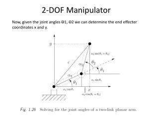
Central Topic - Where is the tool Instructor: Jacob Rosen Advanced Robotic - MAE 263D - Department of Mechanical & Aerospace Engineering - UCLA
Joint/Link Description Lower pair - The connection between a pair of bodies when the relative motions is characterize by two surfaces sliding over one another. Mechanical Design Constrains 1 DOF Joint Revolute Joint Prismatic Joint Link - A rigid body which defines the relationship between two neighboring joint axes of the manipulator Instructor: Jacob Rosen Advanced Robotic - MAE 263D - Department of Mechanical & Aerospace Engineering - UCLA
DH Parameters - Review - Link Length - The distance from to measured along - Link Twist - The angle between and measured about - Link Offset - The distance from to measured along - Link Angle - The angle between and measured about Note: are singed quantities Instructor: Jacob Rosen Advanced Robotic - MAE 263D - Department of Mechanical & Aerospace Engineering - UCLA
Link Parameters (Denenvit-Hartenberg )- Length & Twist • Joint Axis - A line in space (or a vector direction) about which link irotates relative to linki-1 • Link Length - The distance between axis i and axis i-1 Notes: - Common Normal - Expending cylinder analogy - Distance Parallel axes -> The No. of common normals is Non-Parallel axes -> The No. of common normals is 1 - Sign - • Link Twist - The angle measured from axis i-1 to axis i • Note : Sign Right hand rule Instructor: Jacob Rosen Advanced Robotic - MAE 263D - Department of Mechanical & Aerospace Engineering - UCLA
Link Parameters (Denenvit-Hartenberg )- Twist • Positive Link Twist • Negative Link Twist Instructor: Jacob Rosen Advanced Robotic - MAE 263D - Department of Mechanical & Aerospace Engineering - UCLA
Link Parameters - Example Instructor: Jacob Rosen Advanced Robotic - MAE 263D - Department of Mechanical & Aerospace Engineering - UCLA
Link Parameters - Example • Axes • Link Length • Link Twist Instructor: Jacob Rosen Advanced Robotic - MAE 263D - Department of Mechanical & Aerospace Engineering - UCLA
Joint Variables (Denenvit-Hartenberg ) - Angle & Offset • Link Offset - The signed distance measured along the common axis i(joint i) from the point where intersect the axis i to the point where intersect the axis i Note: -The link offset is variable of joint i if joint i is prismatic - Sign of • Joint Angle - The signed angle made between an extension of and measured about the the axis of the joint i Note: - The joint angle is variable of if the joint i is revolute - Sign - Right hand rule Instructor: Jacob Rosen Advanced Robotic - MAE 263D - Department of Mechanical & Aerospace Engineering - UCLA
Link Parameters - Example Link offset Instructor: Jacob Rosen Advanced Robotic - MAE 263D - Department of Mechanical & Aerospace Engineering - UCLA
Link Parameters - Example Instructor: Jacob Rosen Advanced Robotic - MAE 263D - Department of Mechanical & Aerospace Engineering - UCLA
Affixing Frames to Links - Intermediate Links in the Chain • Origin of Frame {i} - The origin of frame {i} is located were the distance perpendicular intersects the joint i axis • Z Axis - The axis of frame {i} is coincident with the joint axis i • X Axis -The points along the distance in the direction from joint i to joint i+1 Note: - For is normal to the plane of and - The link twist angle is measured in a right hand sense about • Y Axis - The axis complete frame {i} following the right hand rule Instructor: Jacob Rosen Advanced Robotic - MAE 263D - Department of Mechanical & Aerospace Engineering - UCLA
Affixing Frames to Links - First & Last Links in the Chain • Frame {0} - The frame attached to the base of the robot or link 0 called frame {0} This frame does not move and for the problem of arm kinematics can be considered as the reference frame. • Frame {0} coincides with Frame {1} • Frame {N} - Arbitrary Convention Convention Arbitrary Instructor: Jacob Rosen Advanced Robotic - MAE 263D - Department of Mechanical & Aerospace Engineering - UCLA
Link Frame Attachment Procedure - Summary • Joint Axes - Identify the joint axes and imagine (or draw) infinite lines along them. For step 2 through step 5 below, consider two of these neighboring lines (at axes i-1 and i) • Frame Origin - Identify the common perpendicular between them, or point of intersection. At the point of intersection, or at the point where the common perpendicular meets the i th axis, assign the link frame origin. • Axis - Assign the axis pointing along the i th joint axis. • Axis - Assign the axis pointing along the common perpendicular, or if the axes and intersect, assign to be normal to the plane containing the two axes. • Axis - Assign the axis to the complete a right hand coordinate system. • Frame {0} and Frame {1} - Assign {0} to match {1} when the first joint veritable is zero. For {N} choose an origin location and direction freely, but generally so as to cause as many linkage parameters as possible to be zero Instructor: Jacob Rosen Advanced Robotic - MAE 263D - Department of Mechanical & Aerospace Engineering - UCLA
DH Parameters - Summary If the link frame have been attached to the links according to our convention, the following definitions of the DH parameters are valid: - The distance from to measured along - The angle between and measured about - The distance from to measured along - The angle between and measured about Note: are singed quantities Instructor: Jacob Rosen Advanced Robotic - MAE 263D - Department of Mechanical & Aerospace Engineering - UCLA
DH Parameters – Standard / Modified Approach Instructor: Jacob Rosen Advanced Robotic - MAE 263D - Department of Mechanical & Aerospace Engineering - UCLA
Central Topic - Where is the tool Instructor: Jacob Rosen Advanced Robotic - MAE 263D - Department of Mechanical & Aerospace Engineering - UCLA
DH Parameters - Review - The distance from to measured along - The angle between and measured about - The distance from to measured along - The angle between and measured about Note: are singed quantities Instructor: Jacob Rosen Advanced Robotic - MAE 263D - Department of Mechanical & Aerospace Engineering - UCLA
Derivation of link Homogeneous Transformation Problem: Determine the transformation which defines frame {i-1} relative to the frame {i} Note: For any given link of a robot, will be a function of only one variable out of The other three parameters being fixed by mechanical design. Revolute Joint -> Prismatic Joint -> Instructor: Jacob Rosen Advanced Robotic - MAE 263D - Department of Mechanical & Aerospace Engineering - UCLA
Derivation of link Homogeneous Transformation Solution: The problem is further braked into 4 sub problem such that each of the transformations will be a function of one link parameters only • Define three intermediate frames: {P}, {Q}, and {R} - Frame {R} is different from {i-1} only by a rotation of - Frame {Q} is different from {R} only by a translation - Frame {P} is different from {Q} only by a rotation - Frame {i} is different from {P} only by a translation Note : was omitted Instructor: Jacob Rosen Advanced Robotic - MAE 263D - Department of Mechanical & Aerospace Engineering - UCLA
Derivation of link Homogeneous Transformation Solution: A vector defined in frame {i} is expressed in {i-1} as follows The transformation from frame {i-1} to frame {i} is defined as follows Note : was omitted Instructor: Jacob Rosen Advanced Robotic - MAE 263D - Department of Mechanical & Aerospace Engineering - UCLA
Derivation of link Homogeneous Transformation Instructor: Jacob Rosen Advanced Robotic - MAE 263D - Department of Mechanical & Aerospace Engineering - UCLA
DH Parameters – Standard / Modified Approach Standard Form Modified Form Instructor: Jacob Rosen Advanced Robotic - MAE 263D - Department of Mechanical & Aerospace Engineering - UCLA
Concatenating Link Transformation • Define link frames • Define DH parameters of each link • Compute the individual link transformation matrix • Relates frame { N } to frame { 0 } • The transformation will be a function of all n joint variables. • Of the robot’s joint position sensors are measured, the Cartesian position and oriantataion of the last link may be computed by Instructor: Jacob Rosen Advanced Robotic - MAE 263D - Department of Mechanical & Aerospace Engineering - UCLA
Concatenating Link Transformation Instructor: Jacob Rosen Advanced Robotic - MAE 263D - Department of Mechanical & Aerospace Engineering - UCLA
Actuator Space - Joint Space - Cartesian Space Joint Space Cartesian Space Actuator Space Task Oriented Space Operational Space Instructor: Jacob Rosen Advanced Robotic - MAE 263D - Department of Mechanical & Aerospace Engineering - UCLA
PUMA Family PUMA 700 PUMA 500 PUMA 200 Instructor: Jacob Rosen Advanced Robotic - MAE 263D - Department of Mechanical & Aerospace Engineering - UCLA
PUMA 560 - 6R 1 2 3 5 6 4 Instructor: Jacob Rosen Advanced Robotic - MAE 263D - Department of Mechanical & Aerospace Engineering - UCLA
Kinematics of an Industrial Robot - PUMA 560 • The robot position in which all joint angles are equal to zero Instructor: Jacob Rosen Advanced Robotic - MAE 263D - Department of Mechanical & Aerospace Engineering - UCLA
PUMA 560 - Frame Assignments - Frame {0} {1} • Assign {0} to match {1} when the first joint veritable is zero. Frame {0} is coincident with Frame {1} • Assign the axis pointing along the 1st joint axis. • Assign the axis pointing along the common perpendicular, or if the axes intersect, assign to be normal to the plane containing the two axes • Assign the axis to the complete a right hand coordinate system. 2 1 Instructor: Jacob Rosen Advanced Robotic - MAE 263D - Department of Mechanical & Aerospace Engineering - UCLA
PUMA 560 - Frame Assignments - Frame {2} • Assign the axis pointing along the 2ed joint axis. • Assign the axis pointing along the common perpendicular • Assign the axis to the complete a right hand coordinate system. 2 3 Instructor: Jacob Rosen Advanced Robotic - MAE 263D - Department of Mechanical & Aerospace Engineering - UCLA
PUMA 560 - Frame Assignments - Frame {3} • Assign the axis pointing along the 3ed joint axis. • Assign the axis pointing along the common perpendicular • Assign the axis to the complete a right hand coordinate system. 3 4 Instructor: Jacob Rosen Advanced Robotic - MAE 263D - Department of Mechanical & Aerospace Engineering - UCLA
PUMA 560 - Frame Assignments - Frame {4} • Assign the axis pointing along the 4th joint axis. • Assign the axis pointing along the common perpendicular if the axes intersect, assign to be normal to the plane containing the two axes • Assign the axis to the complete a right hand coordinate system. 5 4 - The distance from to measured along - The distance from to measured along Instructor: Jacob Rosen Advanced Robotic - MAE 263D - Department of Mechanical & Aerospace Engineering - UCLA
PUMA 560 - Frame Assignments - Frames {4}, {5}, {6} Instructor: Jacob Rosen Advanced Robotic - MAE 263D - Department of Mechanical & Aerospace Engineering - UCLA
PUMA 560 - Frame Assignments - Frame {5} • Assign the axis pointing along the 5th joint axis. • Assign the axis pointing along the common perpendicular if the axes intersect, assign to be normal to the plane containing the two axes • Assign the axis to the complete a right hand coordinate system. 5 6 Instructor: Jacob Rosen Advanced Robotic - MAE 263D - Department of Mechanical & Aerospace Engineering - UCLA
PUMA 560 - Frame Assignments - Frame {6} ({N}) • Assign the axis pointing along the 6th joint axis. • For frame {N} ({6}) choose an origin location and direction freely, but generally so as to cause as many linkage parameters as possible to be zero • Assign the axis to the complete a right hand coordinate system. 6 Instructor: Jacob Rosen Advanced Robotic - MAE 263D - Department of Mechanical & Aerospace Engineering - UCLA
PUMA 560 - DH Parameters - The angle between to measured about Instructor: Jacob Rosen Advanced Robotic - MAE 263D - Department of Mechanical & Aerospace Engineering - UCLA
PUMA 560 - DH Parameters - The distance from to measured along Instructor: Jacob Rosen Advanced Robotic - MAE 263D - Department of Mechanical & Aerospace Engineering - UCLA
PUMA 560 - DH Parameters - The distance from to measured along Instructor: Jacob Rosen Advanced Robotic - MAE 263D - Department of Mechanical & Aerospace Engineering - UCLA
PUMA 560 - DH Parameters - The angle between to measured about Instructor: Jacob Rosen Advanced Robotic - MAE 263D - Department of Mechanical & Aerospace Engineering - UCLA
PUMA 560 - DH Parameters Instructor: Jacob Rosen Advanced Robotic - MAE 263D - Department of Mechanical & Aerospace Engineering - UCLA
PUMA 560 - Link Transformations Instructor: Jacob Rosen Advanced Robotic - MAE 263D - Department of Mechanical & Aerospace Engineering - UCLA
PUMA 560 - Kinematics Equations • The kinematics equations of PUMA 560 specify how to compute the position & orientation of frame {6} (tool) relative to frame {0} (base) of the robot. These are the basic equations for all kinematic analysis of this manipulator. • Notations Instructor: Jacob Rosen Advanced Robotic - MAE 263D - Department of Mechanical & Aerospace Engineering - UCLA
PUMA 560 - Kinematics Equations – Verification Instructor: Jacob Rosen Advanced Robotic - MAE 263D - Department of Mechanical & Aerospace Engineering - UCLA
Frame With Standard Names • Base Frame {B} - {B} is located at the base of the manipulator affixed to the nonmoving part of the robot (another name for frame {0}) • Station Frame{S} - {S} is located in a task relevant location (e.g. at the corner of the table upon the which the robot is to work). From the user perspective {S} is the universe frame (task frame or world frame) and all action of the robot are made relative to it. The station frame {S} is always specify with respect to the base frame {B}, i.e. Instructor: Jacob Rosen Advanced Robotic - MAE 263D - Department of Mechanical & Aerospace Engineering - UCLA
Frame With Standard Names • Wrist Frame {W} - {W} is affixed to the last link of the manipulator - the wrist (another name for frame {N}). The wrist frame {W} is defined relative to the base frame i.e. • Tool Frame{T} - {T} is affixed to the end of any tool the robot happens to be holding. When the hand is empty, {T} is located with its origin between the fingertips of the robot. The tool frame {T} is always specified with respect to the wrist frame {W} i.e. Instructor: Jacob Rosen Advanced Robotic - MAE 263D - Department of Mechanical & Aerospace Engineering - UCLA
Frame With Standard Names • Goal Frame {G} - {G} is describing the location to which the robot is about to move the tool. At the end of the robot motion the tool frame {T} is about to coincidewith the the goal frame {G}. The goal frame is always specified with respect to the station frame {S} i.e. Instructor: Jacob Rosen Advanced Robotic - MAE 263D - Department of Mechanical & Aerospace Engineering - UCLA
Where is the tool ? • Problem: Calculate the transformation matrix of the the tool frame {T} relative to the station frame {S} - • Solution: Cartesian Transformation Instructor: Jacob Rosen Advanced Robotic - MAE 263D - Department of Mechanical & Aerospace Engineering - UCLA