Download
1 / 28
280 likes | 538 Views
SPX - Technical Integration WBS 1.03.03 . Ali Nassiri RF Group Leader SPX Technical Lead Accelerator Systems Division DOE CD-2 Review of APS-U 4-6 December 2012. Outline. Scope Org Chart Goals and Requirements Design Technical challenges Integrated R&D plan Technical risks

E N D
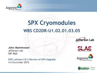
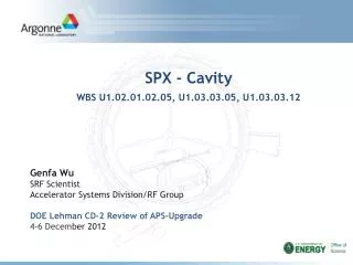
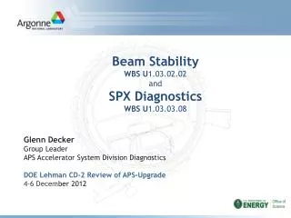
SPX - Technical IntegrationWBS 1.03.03 Ali Nassiri RF Group Leader SPX Technical Lead Accelerator Systems Division DOE CD-2 Review of APS-U4-6 December 2012
Outline • Scope • Org Chart • Goals and Requirements • Design • Technical challenges • Integrated R&D plan • Technical risks • Responses to previous reviews recommendations • ES&H • Summary DOE CD-2 Review of the Advanced Photon Source Upgrade Project 4-6 December 2012
SPX Goal • Provide a short-pulse x-ray system (SPX) delivering few pico-second x-ray pluses to the APS users. This system is based on superconducting RF deflecting cavities operated in continuous-wave mode. • Up to 4 ID and 2 BM beam lines, operation in 24 singlets mode • This system must meet several operational requirements: • Minimize frequency of interruption of user experiments with the deflecting cavities • Be transparent to the storage ring operation with beam when the power to the deflecting cavities is off, cavities detuned and parked at other than 2 K Symmetric 150 mA in 24 bunches 153 ns spacing Long straight section 5 ID (8 meters long) Normal straight section 6 ID ( 5 meters long) Long straight section 7 ID ( 8 meters long) Long taper transition Gate valve Bellows Cryomodule length: ~ 3meters BM ID Cav X-ray Girder 5 Stored beam Sector 5 Sector 7 Sector 7 LSS Layout Revolver undulator SPX cryomodule HOM Damper Girder 1 LOM Damper HOM Damper Input Coupler DOE CD-2 Review of the Advanced Photon Source Upgrade Project 4-6 December 2012
SPX Main Parameters aTo cover more than on SR revolution harmonic bTo allow for reasonable range of SR circumference change base on experimental studies of new APS lattices DOE CD-2 Review of the Advanced Photon Source Upgrade Project 4-6 December 2012
SPX Technical Systems • Two cryomodules with four superconducting rf deflecting cavities in each cryomodule. Each cavity is equipped with a mechanical/piezo tuner, a fundamental frequency power coupler and lower- higher-order-mode waveguide dampers. • Eight 10-kW rf amplifiers operated in continuous wave mode • Eight low-level rf controllers, one per cavity, to independently regulate and control each cavity field • Fiber-based highly-stable phase reference lines distribution for timing and synchronization to LLRF, beam-line lasers and storage ring main rf frequency. • Diagnostics for inside and outside of the SPX zones. • Controls system to provide remote monitoring and control to all SPX subsystems, interfaces to other APS systems, real-time data processing and thorough diagnostic information and tools for faults troubleshooting and postmortem analysis. • Safety interlock system including personnel protection interlocks and access control interlock • A cryoplant with the design capacity of 320 W at 2K and 500 W at 4.5K • Deionized water system distribution DOE CD-2 Review of the Advanced Photon Source Upgrade Project 4-6 December 2012
SPX Cavity Longitudinal and Transverse Impedance Stability Threshold Stability Threshold Dipole impedance in vertical (deflecting) direction (/m) Stability Threshold Monopole stability threshold Dipole impedance in horizontal direction (/m) Dipole Stability Threshold Horizontal dipole Vertical dipole DOE CD-2 Review of the Advanced Photon Source Upgrade Project 4-6 December 2012
RF Distribution Topology • Narrow-band cavities make it difficult to do vector-sum of cavities because of potential large fluctuation of cavities fields due to microphonics. One rf source per cavity mitigates this problem. One rf source/cavity SPX Baseline Centralized (it is not desirable) DOE CD-2 Review of the Advanced Photon Source Upgrade Project 4-6 December 2012
RF Transmitter Configuration • Phase/ Ampl loops • Cavity tuning loop • Interlocks Aux. Controls Master Oscillator Driver Ampl Waveguide Power Ampl LLRF Power Supply/modulator Circulator Deflecting Cavity Small for SC cavities Large for NC cavities ~ 20% to 30% ~ 30 to 40% Due to beam offset ( ) 0 + m PRF = PBeam loading + PCavity detuning + PCavity loss + PWGloss + POverhead DOE CD-2 Review of the Advanced Photon Source Upgrade Project 4-6 December 2012
DOE CD-2 Review of the Advanced Photon Source Upgrade Project 4-6 December 2012
Summary of SPX Cavity RF Power Requirement • SPX deflecting cavity input RF power is between 2.75 kW to 4.43 kW. • Taking into account a 1dB waveguide loss and a 40% RF power overhead, the required RF power varies between 4. 85 kW to 7.81 kW. • SPX preliminary design calls for 10-kW, 2815-MHz CW klystron-based RF transmitter which is currently in the APS-U SPX baseline. • In response to a recommendation by the CD-2 Director’s Review Committee, we will have several opportunities to measure cavities microphonics culminating in SPX0 system in-ring test in 2014 to determine if the required RF power level could be reduced. • We will consider solid-state RF amplifiers for the SPX defecting cavities if the required cavity input power ( including a 40% overhead) is 5-kW or less. • Since the minimal required RF peak power is directly proportional to the maximum peak detuning, we need to have a good and realistic estimate of the peak cavity detuning when determining the required RF peak power. • If the installed RF power is not adequate, the RF transmitter will run against its maximum output power, which would likely result in cavity trip each time the cavity detuning exceeds the estimated peak detuning. DOE CD-2 Review of the Advanced Photon Source Upgrade Project 4-6 December 2012
Technical Systems – High Level RF • Deliver sufficient rf power to eight rf deflecting cavities ( two cryomodules, four cavities per cryomodule). Cavities are operated at 2815 MHz at a nominal 0.5 MV per cavity. • SPX baseline design consists of eight 10-KW CW klystron amplifiers • Required rf power level will be reevaluated once microphonics of “dressed” cavity and SPX0 cryomodule are measured. See Doug Horan’s talk Technical Systems – Low Level RF • Regulate and control individual cavity amplitude and phase of the cavity fields • The LLRF system is partitioned into two separate sector-level LLRF system • Four individual LLRF controllers See Larry Doolittle’s talk DOE CD-2 Review of the Advanced Photon Source Upgrade Project 4-6 December 2012
Technical Systems – Cavities and Cryomodules HOM damper • Deflecting cavities will operate cw at 2815 MHz, using the TM110 cavity mode to produce a head-tail chirp of the beam • Mark II cavity with horizontal waveguide damper on the cavity body utilizes a “dogbone”- shape coupling iris for enhanced damping • The cavity design was guided by various beam-interaction requirements, including single-bunch current limit and coupled-bunch instabilities • Cavity design meets SPX storage ring stabilities threshold limits Ibeam = 150 mA FPC LOM damper See Genfa Wu’s and John Mammosser’s talks DOE CD-2 Review of the Advanced Photon Source Upgrade Project 4-6 December 2012
Technical Systems – Dampers • SPX requires eight deflecting cavities with a total of 16 HOM dampers and 8 LOM dampers • Rf windows are used for LOM and FPC • HOM damper is broadband (~ 2.5 GHz - ~8 GHz) • HOM dampers and cavity have common vacuum Beam induced losses through waveguide ports HOM waveguide LOM: 1.53 kW HOM: 265 W k|| = 0.367 V/pC (σ = 10mm). LOM waveguide Beam pipe: ~ 15W FPC waveguide FPC: 160 W See Geoff Waldschmidt’s talk DOE CD-2 Review of the Advanced Photon Source Upgrade Project 4-6 December 2012
SPX Cryomodule Estimated Heat Load DOE CD-2 Review of the Advanced Photon Source Upgrade Project 4-6 December 2012
SPX Cryogenic System • Cryogenic plant and distribution system • Provides helium at 300 kPa, 4.6 K to the distribution system • The helium is cooled to 2.2 K within each cryomodule by heat exchanger with the 2.0K saturated vapor return stream • The 2.2K, 300 kPa supply is throttled to 2.00K, 3.13 kPa and supplied to the cavities • Cryoplants typically sized for 100% design margin • SPX total heat load per cryomodule is estimated at ~80W • Two (2) cryomodules • SPX production design head load is estimated at 160 W • LHe ( 2.0K) refrigerator is sized for 320 W DOE CD-2 Review of the Advanced Photon Source Upgrade Project 4-6 December 2012
Machine Protection Considerations • Protection of SPX rf system hardware from excessive beam-generated rf power is required. • For machine projection considerations, the beam generated cavity voltage was calculated for pure beam offsets with zero cavity detuning as a function of Qext . DOE CD-2 Review of the Advanced Photon Source Upgrade Project 4-6 December 2012
Technical Systems – Controls Technical Systems – Timing/Synchronization Key Specifications • Integrate SPX system with existing APS storage ring controls, timing and diagnostics • Provide remote monitoring, control, interfaces, real-time data processing environment and diagnostics information and tools for troubleshooting and postmortem fault analysis • Provide stable phase references needed to drive deflecting cavities and measure the effects on the electron beam both inside and outside of the SPX zones • Provide stable phase reference to sector beam lines lasers for synchronization to the x-ray beam pulses See Frank Lenkszus’ talk See Ned Arnold’s talk DOE CD-2 Review of the Advanced Photon Source Upgrade Project 4-6 December 2012
Technical Systems – Diagnostics Inside the SPX zone (Sectors 6 and 7): • Provide transverse beam-centroid coordination so the electron bunch can be put through the cryomodules close to the center of the cavities. • Provide beam-position readbacks at both end of 6-ID chamber. (16 existing BPMs, 6 new) • Quantify the effect of the deflecting cavities by measuring the beam tilt angle at a location downstream of the first cryomodule. (One rf tilt monitor) External to SPX zone: • Measure the beam arrival time with respect to a phase reference and provide this information to a real-time data network for use in the low-level rf controls of the deflecting cavities. (One rf BAT monitor, two rf tilt monitors) • Measure residual emittance increase ( mostly in vertical plan). Use vertical beam-size monitor located at a specific vertical betatron phase relative to the cavities. (One beam size monitor) • Use existing beam position monitors to assure minimal impact of SPX on non-SPX beam lines. • Real-time feed back system upgrade provides significant improvements • Access to phase detectors beam tilt monitors supporting SPX • Interfaced to main and SPX low-level RF (LLRF) systems • 3 db BW > 200 Hz ( correctors only), 1 kHz with LLRF feedback DOE CD-2 Review of the Advanced Photon Source Upgrade Project 4-6 December 2012
Technical Systems – Safety Interlock System • Safety Interlock System comprised of Personnel Protection Interlocks (PPI) and Access Control Interlock System (ACIS). • PPI will address potential hazards to personnel from SPX rf system hardware including rf radiation leakage from open waveguide flanges, contact with high-voltage conductors and exposure to ionizing radiation generated by the klystrons. • The SPX ACIS will include all hardware, software and control system to interface between the storage ring access control interlock system (SR ACIS) and the SPX ACIS. The SR ACIS will issue a permit signal to SPX ACIS only when the SR Zone A is in Beam Permit mode. SPX ACIS functional relationship to other ACISs DOE CD-2 Review of the Advanced Photon Source Upgrade Project 4-6 December 2012
Technical Challenges • Timing and synchronization • Meeting differential mode phase tolerance to keep rms beam motion outside of SPX under beam stability requirements • Maintaining stability of ~ 20 fs rms over 0.1 Hz- 1 kHz for phase reference distribution • Cavity and cryomodule • Operating margin for cavity deflecting voltage and Q • Multi-cavity alignment • Performance of low-loss unshielded intra-cavity bellows • Microphonics compensation on fast time scale • Dampers • Fabrication consistency of SiC tiles to eliminate fracturing • Keeping particulates low ( HOM dampers) • Managing dampers heat load under off-normal conditions • Preventing water freezing in case of total power loss DOE CD-2 Review of the Advanced Photon Source Upgrade Project 4-6 December 2012
Ongoing R&D in Support of SPX Final Design • SPX R&D Goals • Validate SPX concept, critical technologies and mitigate technical risks • Gain experience in design and operation of SCRF system • Demonstrate that SPX system is transparent to the storage ring operation with “parked” cavities • Test and evaluate deflecting cavities, components rf performances • Cavities and cryomodule – collaboration with JLab • Fabrication of Mark II cavities and supporting components • Test and measurement of single cavity in vertical cryostat • Test and measurement of a dressed cavity in horizontal cryostat • Dampers fabrication and high-power tests • Testing of low-impedance unshielded bellows • High power rf system • Assembling two 5-kW/2815 GHz rf amplifiers to support SPX0 cavities power and in-ring tests. • LLRF • One LLRF4 system is on hand (developed in collaboration with LBNL). It will be used to support cavity horizontal test at ANL-PHY ATLAS facility • Timing/synchronization • Collaboration with LBNL to apply their femtosecond timing/synchronization system • Demonstrate stable phase reference to LLRF DOE CD-2 Review of the Advanced Photon Source Upgrade Project 4-6 December 2012
Integrated R&D Plan Design Fabrication Ready for SPX0 cryomodule Chemistry Qualified Fixturing SPX0 Cryomodule Fabrication for 2-cavity @JLab Alignment Cavity/tuner assembly “ dressed cavity” Cavity Vertical Test Bench Test Fabrication Ready for cavity Assembly Tuner 2nd 5-kW Amplifier shipped to JLAB Stack test 1st 5-kWAmplifier Ready for cavity test Jan. 2014 5-kW Amplifier Assembly (2) Dec. 2013 Test with RF load HLRF Dec. 2012 Cryomodule test and qualification @JLab Check Interlocks SPX0 Cavity/tuner Qualified Test with High-Q Emulators LLRF Ready for cavity test Horizontal Test @ANL LLRF Sept. 2012 March 2014 Test with RF load Cryomodule test @ANL Fabrication/Test/Qualification Window and WG RF design Test& Qualification FPC Deliver 2 units to JLAB Thermal/Mechanical design March 2013 Apr. 2014 Thermal test SPX0 Cryomodule ready for ring installation LOM damper test RF power test Dampers WG design Dampers WG Fabrication HOM Prototype Assembly LOM Assembly Complete Test& Qualification Oct. 2014 Deliver 4 units to JLAB Damper SiC material test Install SPX0 and test with beam HOM dampers tests RF power tests March 2013 Jan. 2015 Complete SPX0 testing Finish SPX Final Design Sept. 2015 DOE CD-2 Review of the Advanced Photon Source Upgrade Project 4-6 December 2012
Summary of SPX Technical Risks • Cavity gradient and Q0 degradation • Reduce cavity operating field • Explore in-situ processing • Use electro-polishing and other processing methods • Excessive microphonics • Measure microphonics in horizontal test and in in-ring test • Measure vibration source(s) and their transfer function between cavity and source(s) • 2K/80K heat load is excessive • Develop 5K head shield • Use horizontal test and SPX0 cryomodule test to find the high heat load location and redesign the thermal shield and interceptor • Inter-cavity bellows fail • Extensive test of bellows offline • Develop alternative shielded bellows with low particulates generation • Cavity alignment out of specs • Develop external mechanical alignment for cavities string • Possible damper material failure and excessive particulates • Conducting extensive tests at SPX RF test stand DOE CD-2 Review of the Advanced Photon Source Upgrade Project 4-6 December 2012
Summary of SPX Technical Risks(cont.) • Power amplifier too small to maintain control of cavities fields to specified beam orbit offset • Baseline design is a 10kW klystron-based RF transmitter with 40% overhead. We will reassess RF power requirement during SPX0 in-ring test. • Fast rf interlocks cannot prevent damage to cavities caused by beam –generated rf power • Evaluate in in-ring test • Confirm adequate response time for beam abort interlock • Timing and synchronization • Cannot meet long term common mode or differential mode phase specs • Use beam-based feedback from storage ring BPMs to LLRF phase to compensate • Use Beam Arrival Time (BAT) monitor for beam arrival time (common mode) errors • Cannot meet long term user beam line synchronization specs • Use feed forward from upstream cavity phase to beam line laser phase to compensate • Unknown perturbations (beam loading, microphonics and environmental EMI) • Collect data during the development phase. Work with other systems developers to minimize these perturbations as much as possible. DOE CD-2 Review of the Advanced Photon Source Upgrade Project 4-6 December 2012
Summary of SPX Technical Risks (cont.) • Uncertainty in cavity/cryomodule heat load (not really a cryogenic systems risk, but the biggest risk element in terms of being able to cool the cavities) • Allow adequate system margin • Cryoplant performance fails to meet spec • Thoroughly reviewed, mature plant design, commissioning strategy including vendor participation and system margin. • Operational reliability uncertainty (contamination, rotating machinery failure, etc) • Mature plant design, implementation of proven purification technology, use of mature subcomponent designs (expanders, compressors, heat exchangers), redundant components/hot spares, and anticipated maintenance partnerships with other laboratories (Fermilab, JLab). DOE CD-2 Review of the Advanced Photon Source Upgrade Project 4-6 December 2012
Post CD-1 SPX Technical Reviews DOE CD-2 Review of the Advanced Photon Source Upgrade Project 4-6 December 2012
SPX ES&H • Integrated Safety Management System (ISMS) • APS-U Project following Argonne’s ISMS program requirements • Argonne Integrated Safety Management System (ISMS) Description recently revised and submitted to DOE ASO • Describes framework for integrating ESH requirements with mission objectives • References Argonne LMS procedures which implement specific portions of the ISMS • Identify General Safeguards and Security Requirements • APS-U Project required to follow Argonne’s Operations Security Program (OPSEC) Master Plan • Ionizing radiation, non-ionizing and electrical hazards will be addressed in accordance with ANL rules, procedures and guidelines. • Oxygen deficiency hazards are been analyzed. • Pressure safety is being addressed. • New hazards will be examined and reviewed in accordance with ANL rules, procedures and guidelines per ISMS. DOE CD-2 Review of the Advanced Photon Source Upgrade Project 4-6 December 2012
Summary • Conceptual design of SPX technical systems is complete. • SPX Physics Requirements Document (PRD) is complete and signed off. • SPX Engineering Design Specifications (ESDs) and Interface Control Documents (ICDs) are drafted. • SPX preliminary design is progressing well. • Technical challenges have been identified and are being addressed in the R&D phase in collaboration with JLab and LBNL. • Integration and commissioning plans are being developed. • Safety is integrated into our work planning, test and commissioning. • We are ready for CD2. DOE CD-2 Review of the Advanced Photon Source Upgrade Project 4-6 December 2012