Download
1 / 29
390 likes | 723 Views
Avalanche Photodiodes for 3-D LADAR and Communications*. S. Verghese.

E N D
Avalanche Photodiodes for 3-D LADAR and Communications* S. Verghese *This work was sponsored by the National Aeronautics and Space Administration (NASA) Goddard under the Department of the Air Force contract number FA8721-05-C-0002. Opinions, interpretations, conclusions, and recommendations are those of the authors and are not necessarily endorsed by the United States Government.
Key Technical Contributors • InP APDs • CMOS ROIC
Geiger-Mode: Photon-to-Digital Conversion Pixel circuit Digital timing circuit Digitally encoded photon time-stamp photon Lenslet Array APD 4 mm InP APD Polyimide passivation Photons InGaAsP absorber InP multiplier InP APD Array InP Substrate • Single-photon sensitivity • Low dark-count rate • All-digital readout circuit • Compact and low power • Sub-ns timing CMOS ROIC Device Profile
InP Avalanche Photodiodes • Introduction • Applications • APD Figures of Merit • Read-Out Integrated Circuit (ROIC) • Summary
JIGSAW: Short-range 3-D LADAR imaging* Phase 1 OAV Ladar System Mass: 0.34 kg Volume: 3 liters Power: 5 W Organic Air Vehicle (100-m altitude) • Locate and identify obscured targets within given area of 20 x 20 m • Use angular diversity to maximize penetration of foliage • Register and visualize data • ID target from single pass *Slide courtesy Dr. Rich Marino
RF Deep-Space Links are Power Limited 400 million km GEO Neptune Jupiter Saturn Mars Uranus Pluto Moon Mercury Venus 36000 km 0 10 20 30 40 50 60 70 80 90 100 110 dB GEO Link (R2) • Mars Reconnaissance Orbiter • Launched 8/05 • Ka-band, 32 GHz • 35-W transmit power • Data rates up to 2.8 Mbit/s 3-m Transmit Antenna, Mars Reconnaissance Orbiter 34-m Receive Antenna, NASA Deep-Space Network
Optical Deep-Space Links are Photon Starved Neptune Jupiter Saturn Uranus Mars GEO Pluto Moon Mercury 400 million km 36000 km Venus 0 10 20 30 40 50 60 70 80 90 100 110 dB GEO Link (R2) • Mars Laser CommunicationsDemonstration • 1.06 mm, optical carrier • 5-W transmit power • Data rates up to 46 Mbit/s 0.3-m Transmit Aperture, Mars Telecommunications Orbiter 5-m Receive Aperture, Hale Telescope
InP Avalanche Photodiodes • Introduction • Applications • APD Figures of Merit • Photon Detection Efficiency (PDE) • Reset Time • Dark Count Rate (DCR) • Read-Out Integrated Circuit (ROIC) • Summary
PDE and Reset Time: 1.06 mm APDs Lenslet Array 4 mm InP APD Polyimide passivation Photons InGaAsP absorber InP APD Array InP multiplier InP Substrate CMOS ROIC Hermetic Package Device Profile Figures of Merit: • Probability of Detection (45%) • Reset Time (1.6 ms) • Dark Count Rate (20 kHz)
Mitigating Reset-Time Blinding APD pixel #2 (time-history) 1 2 2x2 Array Trapped Carriers 3 4 Photon rate per APD reduced by 4 Blinded Observing 10 MHz 10% signal loss from signal-flux blockage • III-V Geiger-mode APDs must rest after firing for a hold-off time (tho), also called the Reset Time. • Spreading the signal over many pixels reduces the odds of a signal photon striking a blinded pixel • Eliminating the trapped carriers requires dramatic materials improvements
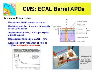
Dark Count Rate: 1.06 mm APDs Lenslet Array 4 mm InP APD Polyimide passivation Photons InGaAsP absorber InP APD Array InP multiplier InP Substrate CMOS ROIC Hermetic Package Device Profile Figures of Merit: • Probability of Detection (45%) • Reset Time (1.6 ms) • Dark Count Rate (20 kHz)
APD Diameter Optimization Desired Size PDE rolloff due to microlens coupling inefficiency Goal: Use APD diameter for minimum DCR and max PDE
Measured Results (1.06-um APDs) Then: Now: Photon Detection Efficiency (PDE) Dark-Count Rate (DCR) Room Temperature Photo-response Profile Effective device diameter Overbias (V) MOCVD-growth run DCR < 30kHz at T = 300K (13um diameter APD) PDE with latest devices 50%
Expected APD Performance (1.06 & 1.55 um) Er Fiber Amplifier compatible (l = 1.55 mm) Yb Fiber Amplifier compatible (l = 1.06 mm) Jan. 2006 Performance Jan. 2006 Performance Near-term GOAL Near-term GOAL InGaAsP/InP Epitaxy InGaAs/InP Epitaxy 55% 50% 10 kHz 10 kHz Higher PDE and reduced loss 0.06 -0.25 dB -1.0 dB 0.016 -0.07dB -1.0 dB DCR X Reset = 0.03 Zero-bkgnd Blockage: -0.14 Microlens loss: -1.5 dB DCR X Reset = 0.12 Zero-bkgnd Blockage: -0.5 Microlens loss: -1.5 dB
LDES Receiver Test Bed Receiver Workstation: PPM Demodulation Turbo Decoding Display and Diagnostics Avalanche Photodiodes: Single-photon arrival timing Receiver Sync Board: Clock synchronization Frame synchronization APD ROIC emulation
Current development in LADAR APDs InP 5V SOI 2V SOI Carrier wafer Metric Requirement • Uniformity • 256x64, 50 mm • 3D Integration • Fast Reset, Counting, Low Jitter, Caching • Other Materials • Increased Array Size • Reduced Pixel Size • Enhanced Processing, Functionality • Spectral Coverage
InP Avalanche Photodiodes • Introduction • Applications • APD Figures of Merit • Photon Detection Efficiency (PDE) • Reset Time • Dark Count Rate (DCR) • Read-Out Integrated Circuit (ROIC) • Summary
3D Ladar Imaging at 1.06 mm Array Readout Array Readout 1 2 32x32 GM-APD Array 3 4 Conventional LADAR Array Concept: Rotatable 3D Image • 1.064mm Nd:YAG mchip laser • InGaAsP/InP APDs on CMOS Blinded (> 50us) Observing (< 1us) (Range Gate) Detection probability color code • All pixels armed synchronously • Low duty cycle (PRF dependent)
Laser Communications at 1.06 mm 1 2 8x8 GM-APD Array 3 4 LaserCom Array Concept: Mars LaserCom MTO/MLT (cancelled) Optical Downlink • 1.06 mm Yb-doped fiber amplifier • InGaAsP/InP APDs on CMOS Observing LDES • All pixels armed asynchronously • 100% duty cycle
Mars LaserCom ROIC Block Diagram • Single-clock input (TS_CLK) • Modest area and power consumption • User friendly (FPGA compatible, self-test, etc) CMOS ROIC APD array Lenslet array Digital timing circuit ~ 2 Vpp Encodedphotonarrival time APD Photons ROIC Pixel Circuit Design Guidelines: ROIC Requirements: • Arm and disarm APD • Record time of photon arrival • Record location of photon arrival
Mars LaserCom Read-Out IC Concept for Asynchronous APD Pixels (Jan ‘04) BYPASSED BYPASSED Packaging and Test Verification (Jan ‘05) 0.35-um CMOS Fab Pixel Cell Layout Wafer-Probe Test Structures Tested on Logic Analyzer at 311 MHz MLCD ROIC Mirrored Copy Definition of Chip Architecture • Mates to 8x8 InP APD array • Rev2 chip: operating in test-bed Simulations and Layout
Packaged LaserCom ROIC 0.5 in Package (lid removed) Alumina Interposer LVCMOS — LVDS Translator Chip CMOS ROIC 2 in 0402 Cap
APD active area (small ~10 um diam.) Demonstrated < 2um alignment error Submicron alignment in development Micro Lens Array Alignment APD array CMOS ROIC Lenslet array: 8x8 100-mm pitch GaP Lens InP APD Ray-trace Microlens-Alignment Challenge: Photo Absorber Active Alignment for Low Loss APD with u-lens Active Alignment Diodes CMOS ROIC Alumina Interposer
MIT/LL design; Kyocera fab Hermetic with integrated TEC 70 high-speed pins (< 6 GHz simulated) Package for Mars LaserCom ROIC 160-pin Pin-Grid-Array Package Kovar housing Ceramic package CuW heatsink Kyocera (160 PGA) MLCD Package w/ Rev2 ROIC & APD
Current Development in APD Read-Out ICs Mapping LADAR Fabricated ROIC Planned ROIC Other LADAR LaserCom Two styles of ROIC design: 100,000 • Low PRF (<< 1 MHz) • High peak power • Background rejection • Large pixel count • Most LADAR applications • High PRF (> 1 MHz) • Average power (energy on target) • Modest background rejection • Smaller pixel count • Most LaserCom applications Saturation Flux = 1011 photons/sec 10,000 256x64 109 photons/sec Array size (pixels) 128x32 1000 107 photons/sec USD_32x32 32x32 105 ph/sec 100 8x8 NbN? 10 kHz 100 kHz 1000 kHz Pixel refresh rate or PRF (Hz) PRF = Pulse Repetition Frequency ROIC = Read-Out Integrated Circuit
Dual 128x32 ROICs in MLCD package • Two overlapping 128x32s (50-um pitch)
InP APDs: Summary • We built and demonstrated integrated InP APD arrays for LaserCom and LADAR • InGaAsP/InP for 1.06-um wavelength • InGaAs for 1.55-um wavelength (less mature) • Current focus: • Increasing Photon Detection Efficiency • Decreasing Dark Count Rate • Hybrid-assembly of InP arrays with Si CMOS enables: • High fill-factor photon counters (up to 4kpixels) • Compact, low-power sensor (plugs into a pc board)
End S. Verghese
Receiver Development Example (MarsCom) MIT-LL Industry Physics Oakley, Vineis G83 InGaAs Growth Epi Vendor APD design & modeling Smith Donnelly InP wafer fabrication Photodiode Vendor Duerr, McIntosh, Hopman G83 Wafer-probe Package, Test CMOS, PCB Mars LaserCom—LDES Contract Mfg Div8 Hopman, Hamilton 1.06-um test-bed 1.55-um test-bed Mars Div6,9 System Analysis System Integrator LDES Candell, Boroson MLCD Program Office