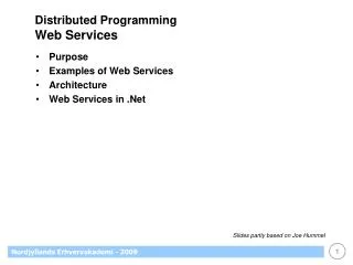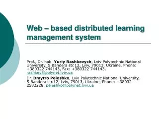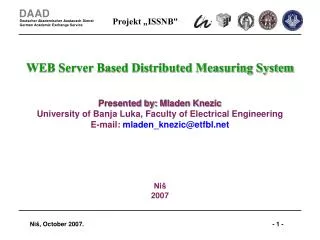
Web services-based collaborative system for distributed engineering
Web services-based collaborative system for distributed engineering. Adam Pawlak Paweł Fraś Piotr Penkala * Silesian University of Technology Inst. of Electronics, Collaborative Engineering Group Gliwice, Poland also Evatronix SA

Web services-based collaborative system for distributed engineering
E N D
Presentation Transcript
Web services-based collaborative system for distributed engineering Adam Pawlak Paweł Fraś Piotr Penkala * Silesian University of Technology Inst. of Electronics, Collaborative Engineering Group Gliwice, Poland alsoEvatronix SA PRO-VE'089th IFIP Working Conference on Virtual Enterprises Poznań, Poland, 8-10.09.2008
Outline • Collaborative engineering for distributed product development • Challenges in collaborative design • MAPPER project objectives and approach • MAPPER collaborative infrastructure • Requirements for distributed tool integration • TRMS - Tool Registration and Management Services • New TRMS architecture • Deployment of TRMS • Conclusions
Collaborative engineering is an innovative method for product development which integrates widely distributed engineers for virtual collaboration. [Cutkosky, MADEFAST, Communicat. of the ACM, Sept. 1996] shared eng. data real-time communicat. interactivity Objective: distributed design of the optical seeker
Why collaborative engineering in electronics • Time to market vs design complexity is since „ever” the most significant factor for new product creation • Thus, increase of design productivity is one of the major objectives within the SoC domain resolved by: • Structured design methodology with IP design reuse • Designing on higher levels of design abstraction • Collaborative design is another approach allowing to increase design productivity of electronic systems with: • Easy and close collaboration of widely distributed engineers being experts in different domains and in different design flow phases • Controlled remote access to expensive design tools, etc.
Infineon’s pan-European distribution Courtesy:Dr. Matthias Bauer, Infineon Technologies
Our motivation for collaborative design Supporting integration of SMEsinto complex design inter-organisational workflows
Selected Challenges in Collaborative Engineering • Establishment of an efficient collaborative engineering environment requires solving at least the following problems: • Collaboration with organisations protected behind firewalls • Data format conformity, etc. • Easy tool integration with standard support for: • Tool description • Design task description • Workflow description • Secure design data transfer • Support for human actors – engineers collaborative actions • Appropriate collaborative workspaces • Advanced synchronous and asynchronous communication
SMEs collaboration perspective • In this work we take an SME perspective for companies distributed engineering collaboration towards a common product.
TRMS - Secure integration ofdistributed tools • Secure integration of distributed design tools was the reserch goal of the Collaborative Engineering group at SUT since ~2000 • Architecture of TRMSv1 was the first result achieved withing the EU project ECOLLEG
E-COLLEG Tool Registration and Management Services l TRMS operation protocol: a: tool registers with profile b: user asks for tool with constraints c: registry checks constraints and returns profile d: user lunches tool with input and output e: tool fetches input and processes outputf: destination fetches output Animation
MAPPER context • We have addressed our didributed colaborative design problem in the context of the EU project MAPPER • MAPPER - Model-based Adaptive Product and Process Engineering FP6-2004-IST-NMP-2 Project No 016527 09.2005-02.2008 http://mapper.eu.org
Problem statement for MAPPER The core problems in the area of faster and more flexible design and manufacturing(agile engineering) concern: • Quick and inexpensive formation of networked manufacturing organisations; • Achieving concurrency in all operations; • Bridging the gaps between heterogeneousknowledge, processes, systems, services, and ways of working; • Support rapid reconfiguration of required processes and productsto accommodate diverse and changing needs and opportunities; • New, cross-partner knowledgewhich continuously created and must be shared, executed on and managed.
Challenges in collaborative design • Concurrency in all operations, increasing design efficiency and decreasing time-to-market. • Quick and inexpensive formation of networked design organisations. • Processes and products should be rapidly reconfigured to accommodate diverse and changing needs and opportunities. • Change management across the entire design chain requires coordination of individual changes and support for iterative adjustments. Collaborative product, process and service engineering must thus be managed and performed across networked organisations. • Integration of tools of remote groups of engineers with adequate for industry solutions for: security, distributed inter-organization workflows, and remote administration of users and tools.
The Vision of MAPPER In 2015, agile design and manufacturing companies can inexpensively form collaborative networks and quickly adapt to market demands.
Scientific and technological objectivesof MAPPER O1:Reconfigurable visual enterprise models of products, processes and other enterprise aspects; O2:Participative engineering methodologies, enabling joint product and process design, interdisciplinary and inter-organisational collaboration throughout multiple product life-cycles; O3:Customisable work environments for different stakeholders, roles and tasks; O4:Secure collaboration platform, enabling enterprises to access each others engineering tools and product data in an open, yet secure manner; O5: To develop and assess three industrial use-cases, and to validate the overall MAPPER approach: - automotive industry (Fiat) and automotive components supplier (Kongsberg Automotive, SWE, N, PL) - electronics industry (IP components supplier, Evatronix, PL)
Participative methodology Standard-based Interoperability Framework Customisable work environments Reconfigurable models Secure service integration platform MAPPER approach Integrate enterprise modelling, human-centred methodologies, collaborative customisation, and secure, distributed tool invocation, into an open, visual, holistic, and reconfigurable collaboration platform
Participative engineering methodology • A method of engineering involving personnel from several areas, possessing different knowledge and skills, responsible for performing various roles in an engineering process. • This methodology aims at integrating product, process and service engineering and have the components: • Networked manufacturing enterprise modelling • Formation and operation of sustainable collaboration • Inter-organisational learning • Multi-project portfolio management
Reconfigurable models • Active knowledge modelling • An approach used to construct live networked manufacturing enterprise models. • AKMs describe the relevant resources, aspects, views, methods and rules to externalise and facilitate knowledge-driven, adaptive collaboration and learning. • Visual modelling and visual scenes. • Visual modelling as a more powerful representation means for sense making: in using systems and in modifying systems.
AKM model of a distributed collaborative design realised by two SMEs
Secure service integration platform • Basic services needed for collaborative enterprise modelling and execution • Modelling services • Model execution services • Collaboration services • Secure tool integration services Secure services-based collaboration platform that enables companies to access shared engineering tools and data on products in a user and secure collaboration friendly way is the goal.
Customizable work environments • User interfaces integrating all the software and information needed to perform a particular task • Packaging functionality according to the user needs and expectations • Customisation and contextualisation • Flexible work environments adaptable for various partners, roles and tasks • The collaborative platform should enable companies offering (e.g. design) solutions and their customers to commonly adapt and configure their work environment
Layers of Services on Top of AKM MAPPER approach towards CWE -2-
Requirements from MAPPER • AKM - Active Knowledge Model paradigm • Services context from MAPPER • Integration within MAPPER collaborative platform • Profound requirements engineering process • SourceS of requirements: – Evatronix and advICo engineers • Reflections from the SUT R&D team • Ethnografic fields studies at companies sites done by social sciences experts
Requirements modelling as AKM • Requirements from Evatronix modelling in METIS • Social scientists were performing ethnographic field studies. Observations and conclusions were assembled in reports that were provided as additional requirements to research & technology teams working on the collaboration infrastructure
TRMS development path TRMS 1 E-Colleg result application ANTS transport mechanism partial firewall crossing TRMS 1.1 initial version for MAPPER application own transport mechanism no firewall crossing 2003 TRMS 1.2 developed in MAPPER applet own transport mechanism service-based functionality 2005 2006 TRMS 2 new architecture application http/https transport mechanisms firewall crossing 2007
GTLS Global ToolLookup Service • Responsible for management of elements of the environment and security policy • GTLS is the only TRMS component accessible from the Internet • Communication broker Client – Tool Invoker GTLS plays a role of a broker and a temporary repository in a communication between a Client Application and Tool Servers. • GTLS cooperates with SQL data base DB contains information on users and their privileges, TSs, registered tools, and workflows. • (Design) data management • Implemented as a set of Web Services (Apache AXIS).
GTLS (main) web services Administration Administration services are responsible for registration and modification of data on users and their privileges, elements of the system, as well as, information on accessible tools and machines that make them available. User and Server Authentication Upon user/designer logs in, a new session is created and a user receives its key. Tool Servers are authenticated automatically upon their invocation. Task Management Each tool that is expected to be accessible over the network needs to be registered and placed in the task queue. Registration involves determination of necessary data for tool invocation. Workflow Management A workflow constitutes a set of tasks that are in the task queue. Current implementation supports sequential workflows.
Tool invoker • Responsible for: • Fetching of input data • Program invocation • Dispatching of console messages • Sending of results • Constant connection with GTLS isn’t required
Client application • Two versions: Tiny vs. Fat Client (adminstrator) • Constant connection with GTLS isn’t required (one may invoke a design task and switch of the client application)
TRMS 2.0 newfunctionalityversusversions 1.x • Support for work in the networks with NAT and firewalls Communication is always initiated by either tool servers or client applications. Tool server (tool invoker) polls for a job to do. • Support for long jobs Client app can be switched off during the job execution on a tool server. Actual job status and output results are available during the consecutive log-in. • Support for a sequential workflows Next task is executed under the control of GTLS after the previous one is over. • Access to console output messages of the invoked tool • A number of users can access and control the execution of a task
Used technologies • Java SE 6 • Apache Tomcat 5.5 (lub 6) • Apache AXIS 1.3 (lub 2) • Hibernate • HSQL (MySQL, PostgreSQL) • appframework, jdesktop
TRMS 2.0 achievements (technology and architecture) • New TRMS architecture is based on Web services thus supporting (MAPPER) integration with other Collaborative Working Environmnts • Both applet and application versions are available • Secure transmission channel, optional encoding using keys • Transfer based on standard https or http protocols • Deployed in MAPPER pilots 2 and 3 • (intra-) and inter-company distributed tool integration
TRMS 2.0plans • Extend functionality and user interface (e.g., user awareness, event notification service) • Development of a more advanced workflow management system
TRMS deployment USB PHY design challengesin MAPPER • Experts were needed from two different designers’ worlds: analogue and digital • The design environment is distributed (2 companies, 3 locations) • Problems with interoperability of current design tools (different domains, different file formats)
Evatronix and advICo workflows Each company has well defined own design flow advICo Design Flow Component specification Development Verification Product preparation
Evatronix Design Flow advICo Design Flow Analog and Digital Block integration Distributed design and verification between advICo and Evatronix Integration of USB PHY digital and analogue design flows was a problem
Pilot 3 USB-OTG-PHY design coverage Integration &Verification of whole USB PHY design was a scope of the Pilot 3
Pilot 3 – step 2 Digital waveform view
Pilot 3 – step 2 Analog waveform view