Download
1 / 15
150 likes | 186 Views
Update on recent tests of MimoStar2 sensors and testing plans for MimoStar2 and MimoStar3 prototypes. Includes results, testing modes, discharge time findings, upgraded test system details, pixel array scan, equilibrium studies, self-biased structure conclusions, and final remarks.

E N D
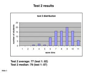
MimoStar2 Current test results at LBL Update on recent tests of MimoStar2 sensors performed at LBL
Plans for testing MimoStar2 & MimoStar3 TESTING PLANS: • Preparations for testing of faulty pixels on MimoStar2 and MimoStar3 prototypes • Possibility to stop on a pixel and test its sensitivity to external signals (LED light) • Currently no prototypes with faulty pixels are on hand • Test PCB for MimoStar3 has been submitted and is expected to arrive in 2 weeks • In the mean time we could bond MimoStar2 and re-verify if dead-pixels are related to handling (time constraints)
Testing modes/patterns • Static mode (stopping periodically on one selected pixel) • Dynamic mode (continuous readout and with acquisition of samples for the selected pixel only)
First tests of discharge time • No cooling in the system (no temperature control) • Small protective box enclosing sensor and RDO board • Pause on a pixel in the static mode limited to 3 frames • RESULTS: • Very short discharge time is static mode (~0.3 ms time constant) • Short discharge time in dynamic mode • STD ~ 23.2 ms (average) • RAD ~ 11.0 ms (average) Discharge time on the order of 100 ms was expected based on measurements performed in Strasbourg in the STATIC mode
Upgraded test system • Chiller and a radiator blowing cold air on the DUT • Large light-tight box containing the setup • Infrared temperature sensor for continuous temperature monitoring • No restrictions on the programmable test pattern • Duration of pause up to integral factors of 2×218
Discharge time constant • @ 30 °C • STD 262 ms (average dynamic) 175 ms (static) • RAD 132 ms (average dynamic) 100 ms (static) • Consistent with results from Strasbourg Measured in Strasbourg: Time constant of 150 ms (increases up to 1.16 s at -10°C)
Scan of the pixel array • Limitation of the system on continuous acquisition • in full frame mode data set is limited to 5-6 continuous frames (due to RORC interrupts) • Only one pixel readout at a time • But it can be scripted and looped • Room for improvement (more pixel per frame) • Could be implemented when a need arises (time constraints) 14 hrs of data taking
Pixel array uniformity • Information on uniformity of discharge time • uniformity on uniformity of leakage currents • Somewhat uniform (except for the first two rows of pixel at the edge of the sensor – also visible with an oscilloscope)
Additional studies of equilibrium • Tread/Tframe↑ Vout↑ • frequency ↑ Vout↓ • Tread/Tframe↑ time constant ↓ During our recent phone conference (13Sep2007) Wojtek clarified that practically the same equilibrium should be expected in both modes – this explains all of the above observations If the readout phase “injects charge” (clock feed-through ?) and removes it at the end of the phase, we should be able to change the equilibrium in one pixel by stopping on it for an extended time not true when assuming different equilibria
Conclusions on the self-biased structure • Voltage drop at the sensor output due to readout is 1.5 V => 500mV at the diode level • It’s the same equilibrium in all cases, especially in static and dynamic readout modes Time constant 64 frames = 108 ms equilibrium Time constant 220 frames = 374 ms
Reference frame Pause on a selected pixel End pause and resume operation One frame after resuming operation
Final remarks Results prove that there is the same equilibrium in static and dynamic mode Questions to designers: Are there three columns active in each sub array at any given time (being prepared for readout)? (This is just for better understanding of the operation of the MimoStar2 sensor)
Hot pixels (3/3) hot pixel regular pixel