Download
1 / 6
60 likes | 165 Views
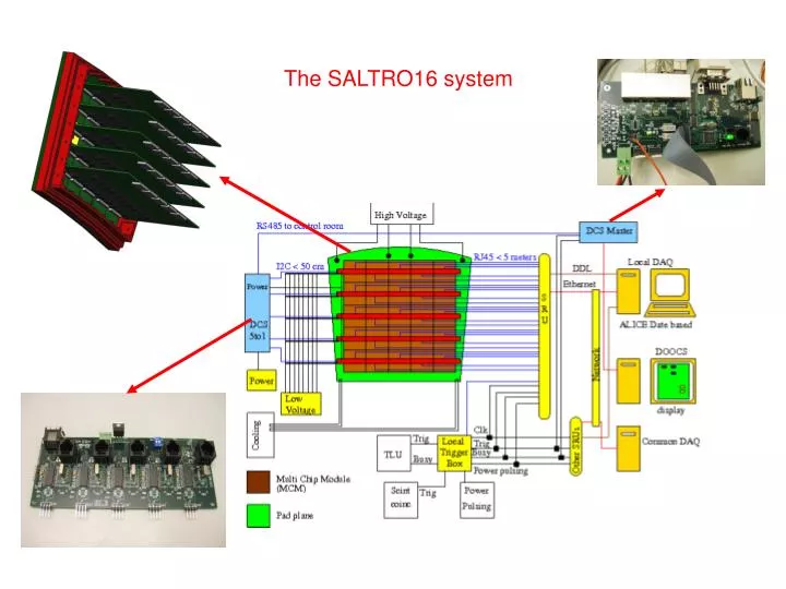
The SALTRO16 system. From ALTRO to SALTRO16 A decrease in size by a factor 40. FEC with 8 ALTRO. 190 mm. MCM with 8 SALTRO. Carrier Board. 32.5 mm. 8.9 mm. 12 mm. 170 mm. 25 mm. 25 mm. 17 cm. 8.9 mm. MCM. 32.5 mm. CPLD. FEC. 19 cm. With mounted chip. Pad Pad Module. Side

E N D
From ALTRO to SALTRO16 A decrease in size by a factor 40 FEC with 8 ALTRO 190 mm MCM with 8 SALTRO Carrier Board 32.5 mm 8.9 mm 12 mm 170 mm 25 mm 25 mm 17 cm 8.9 mm MCM 32.5 mm CPLD FEC 19cm With mounted chip PadPad Module Side views of an MCM
The Carrier Board Carrier Board with SALTRO chip mounted Bottom side of the Carrier Board with tin balls Test Socket Bonding machine
The MCM-development board (stand alone board) CPLD 14.5 cm Place for SALTRO 20.6 cm The MCM-development board has been sent to Brussels together with an SALTRO-chip in CQFP208 packaging. An SRU has also been sent to Brussels. Purpose: Develop firmware for communication between the CPLD (Yifan Yang) on the MCM-board and the SRU (Fan Zang). Fan Zang has arrived in Brussels on the 6.1 and will stay until the 25.1 Work program: Program the CPLD Communicate with the SRU Mount the SALTRO-chip Communicate with the SALTRO
Connectors The problem with the male connectors on the upper side of the MCM-board is that the female partner can not be mounted on a vertical LV-board. This has forced us to introduce an adaptor board and a pair of additional connectors, which are suited for such mounting. The MCM-board plus the adaptor board can be regarded as a unit, which will not be separated.
Present status and future plans Item Status Plans/purpose Carrier Board (CB) 1st SALTRO-chip succesfully Bonding ongoing mounted Test Socket (TS) Delivered Setup of test system Test Socket Board (TSB) Design ready; mounting of components, PCB order week 3 tests of 1st CBs MCM development board Ready, has been sent to Functionality tests; (dMCM) Brussels Develpment of firmware for communication CPLD-SRU SRU Sent to Brussels MCM Final Board (fMCM) Design essentially ready Finalize after tests with pMCM and delivery of connectors LV Prototype Board (pLV) Ready Functionality tests; LV to TSB test I2C communication LV Final Board (fLV) Design essentially ready Finalize after tests with pLV Detector Control System Master Board Ready tests ongoing 5to1 Board Ready tests ongoing