Download
1 / 17
170 likes | 416 Views
CHARA AO WFS Design. JDM (+LS,MJI) 2012Sep06 v 0.1. WFS Design Goals. Subaperture geometry matched to Cilas DMs under consideration Camera frame rate 1 khz High throughput (few reflections) Lenslet plane will be conjugate with secondary mirror location

E N D
CHARA AO WFS Design JDM (+LS,MJI) 2012Sep06 v0.1
WFS Design Goals • Subaperture geometry matched to Cilas DMs under consideration • Camera frame rate 1 khz • High throughput (few reflections) • Lenslet plane will be conjugate with secondary mirror location • Filters: Bandpass filter (no ADC) and notch filter (laser diode beacon) • Off the shelf components, when possible
A. Subaperturegeometry Spacing 0.20m 18 spots Spacing 0.17m 30 spots Spacing 0.14m 44 spots Cilas DM 31 Actuator (were these ellptical?) Cilas DM 61 Actuator
B. Camera Rate • Design goal of 1 Khz frame rate on camera • Good correction for fast seeing on bright targets • Avoid saturation for bright targets • Run camera in photon counting mode • Assuming AndoriXon Ultra 897, 1 khz == 90x90 pixels in fastest readout mode • Issues: • Need field/pupil stop for ‘cropped sensor mode’ • Shutter? • Where to put subarray if no shutter (de factor frame transfer ccd)?
D. Location of Lensletplane Location of focus Field stop 5” (~100micron) Lenslet goes here Achromatic doublet F=7.5mm, AR coated Light from parabola Collimate beam so aperture is 1.5mm Input pupil (secondary) imaged here: 7.2 mm from collimator
E. Filters: bandpass + beacon notch Lenslet goes here ~5mm Light from parabla Filter(s) could go here. Must be interchangeble
E. Off the shelf components • OKO C-mount hexagonal lenslet • Spacing 0.3mm, f=18mm • Used for all calculations • Thorlabs f=7.5mm achromat
Unresolved Design Issues:Lenslet • Standard OKO lenslet has good features • Off the shelf • C-mounted • AR coated • FOV of each lenslet is about right (5.2”) • Some issues • Over sample PSF a bit more than necessary (3.2pixels FWHM), which means more dark noise than necessary when closed loop • Requires reading out 90x90 for 0.2m aperture or 130x130 (600Hz) for 0.14m apertures (if we want 0.14m apertures we probably require custom lenslet) • Loses ~15% of light in the edges because circular lenses not hexagonal • Custom lenslet run will likely be 10000-20000 euros • If custom lenslet has f<18mm, then requires major modification to the CCD window assembly and mounting (this will happen if we want lower sampling on the 16micron pixel CCD) • Hexagonal or rectangular lenslets? • Is diameter 5.2” enough field of view (+/-2.6”)? • If we don’t get lenses that fill, do we need a chrome mask to eliminate light spillover?
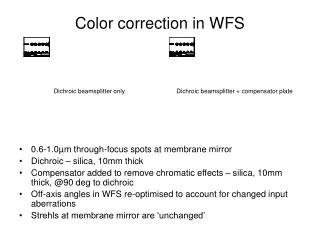
Unresolved design issues:Bandpass Filters In front of focus • In converging beam – but surpisingly this seems to correct downstream aberrations in collimating doublet (but depends on which doublet is chosen – not GENERAL result) • All filters must be matched to not change focus position • Can use off the shelf (larger format possible) • Space to mechanize • *might* compromise acquisition camera sensitivity (throughput/image quality -- TBD) Behind focus • In collimated beam (good) • Must be smaller (off the shelf?) • Harder to exchange but still possible probably (hard to mechanize) • Very tight fit for two filters (notch+bandpass) but possible probably
Notes on Camera Modes Baseline design: • Saturation occurs of V= -0.5mag (no ND filter needed) • 1 count per pixel (peak) for V=12.5 • Noise: 1.5 dark counts per 5”x5” FOV lenslet (but after we close loop we can focus on 2”x2” region which has only 0.25 dark counts per frame) • We have to run always in 17Mhz multiplication mode and will adjust adjust gain for each object • For FAINT stars we should integrate longer than 1ms to improve SNR since clock-induced counts occur per FRAME not per second for this device • Optimal subarray location is not clear • minimize blurring of image during readout (assuming we have no shutter) • Probably need camera to test if offsetting subarray is still fast and leads to “frame transfer ccd” readout • Should we just get shutter? Will it work in for 1 khz for years?
Other Questions • How to deal with wandering pupil due to poor coude alignment? • Do we build in ways to deal with this or rely on good coude alignment? • Could mount WFS assembly to pivot around hole in center of AQ mirror. This would allow a pupil shift without changing upstream tilts. But probably not so easy to do at the level necessary (ie pivot wander <100microns on large mount with camera, etc). • The hole in the AQ mirror will act as our field stop.. • But if we can’t get the hole small enough we could bond a pinhole. Important to have a field stop here to match field of view of lenslets(~5”) • Not sure we can buy a AQ mirror with such a small hole • one vendor I contacted has limit of 1.3mm • Should we allow for off-axis guiding? • I think yes, which means large angular throw using encoders for either fold mirror or parabola
Next steps • Is basic design architecture ok? • Problems? Concerns? Risks? • Decide what options we want to include for trade study for presentation to critical design review • Do sensitivity calculation • simulation of wavefronts, camera detection, wavefront reconstruction, and resulting performance (TT only, TT+AO) • Get quotes for custom items • Do test on lab camera of critical issues • Confirm readout speeds, noise properties, latency • Check mechanical constraints on window • Proceed to design study of acquisition camera/optics • Proceed to design for the beacon/stimulus/alignment system to see how it impacts design of WFS • Check mechanical layouts • Clearance with dicroic changer, other beams, size of table, placeholder for fiber injection module