Download
1 / 26
260 likes | 288 Views
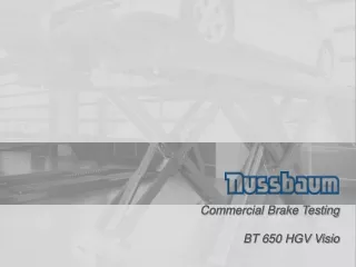
The BT 650 HGV Visio is a comprehensive brake system analyzer for trucks up to 18 tons axle weight. It includes a PC-based software with customizable testing procedures, automatic error checking, and compatibility with VOSA database. The system comes with rollers suitable for class IV and VII applications, and accessories like rugboard, lifting device, weighing device, cover plates, and more.

E N D
Commercial Brake Testing BT 650 HGV Visio
Brake system for trucks • BT 650 HGV Visio basic scope of delivery • BT 650 HGV Visio Accessories
Brake System BT 650 HGV Visio Part No. 0986400C71N • Description: • BT 650: 18 tons axle load, 1 test speed (2,5 km/h) • Level rollers suitable for class IV and VII application • Brake system analyser for trucks up to 18 tons axle weight respectively. Wheel size from 10" to 20". PC based, prepared trucks. Automatic re-start with adjustable start-up time. Asterisk triangle (star/triangle) start, time delayed starting of the rollers on one side. Anti-slip function with adjustable slip limit. Rollers plastic coated, test-stand frames hot galvanized. Automatic error check routine. • Easy to handle software based on Windows XP. All results can be saved locally and can also be sent XML into a network. All results also can be displayed and printed as graphics. • The operator is able to create own testing procedures - the test program itself is a complete full automatic procedure. • VOSA database included with the software package. • Scope of delivery: • Roller set 480 mm centre roller to centre roller • Control cabinet • Cable roller set to control cabinet: 20m To be prepared by customer: Foundation based on foundation drawing Power supplies connection (18 kW, 400 V, 50 Hz)
Brake System BT 650 HGV Visio as a test lane Based on our new developed electronic components, you have the opportunity to extend the single truck brake tester „BT 650 HGV Visio“ to a complete truck test lane: • Roller set: 18 tons, 1 speed • Communication package: PC, monitor, printer, remote control, software • Optional accessories: • Rugboard • Lifting device for roller set • Weighing device • Cover plates • Pit securing device • Brake pressure sensors • Pedal force meter • Additional analogue display • Load simulator device • Four wheel drive • Slip plate: 10 tons max. wheel load • Hydraulic plate detector: Stand alone unit
Available accessories „Cover plates“ for Pit Installation Article-Number Description 1 987 009 B03N Cover plate right sides (Installation in pit) 1 987 009 B04N Cover plate left side (Installation in pit) Description: Installed on the side of the roller set if brake tester is to be installed in a pit.
Communication –PC-Control Unit Description PC-Cabinet complete with PC, mouse, keyboard, 17” TFT, colour ink printer and software, connecting cables and IR-remote control Description: The PC control unit uses the test lane software to control all testing sequences on the unit The user is guided through the testing sequences with the aid of the software and can also configure a user defined test sequence, or the VOSA data base. All results can be saved on the computer. The test lane can be linked to a network through the PC.
Communication –Remote Control Article-Number Description 1 687 246 021N IR-Remote control, to do a brake test in manual mode Description: A remote control device is always recommended for use with a truck brake tester. All necessary functions can be individually activated and/or displayed. If two test lanes are situated side by side, each remote control can be allocated to its respective test lane.
Hardware components -Remote Touch Pad Article-Number Description 0 986 400 U18A Touch Pad as remote communication. PC with WLAN is necessary. Description: Rugboard with accessories can be placed in the drivers cab during testing. All data can be inputted using the touch screen and the live test can be observed. A charger and WLAN-router complete the package.
Available accessories“Lifting device” Article-Number Description 1 987 009 B9SN Lifting device to lift the complete roller set for about 200 mm out of the pit Necessary accessories 1 987 009 C06N Weighing device underneath the roller set (8 sensors) Description: Vehicles with a tandem axle cannot create enough brake force on the rollers while testing on the rear axle (axle beyond the tested axle) is absorbing a high percentage of created brake force as it is standing on the ground / concrete. By lifting up the tested axle up to 200 mm, additional pressure is created on it. Therefore brake force is increased on the axle and a good brake test can be achieved. Additionally, as already mentioned, several loads can be simulated.
Upgrade kits„weighing device“ Article-Number Description 1 987 009 C06N Weighing device underneath the roller set (8-sensors) Description: The 8 – sensors weighing device is required to calculate the weight of the tested axle. The axle weight is necessary to calculate the deceleration (in %) as well as the brake delay (in m/s²). Mandatory requirement! The weighing device is also a necessary feature to enable the VOSA software to be used correctly.
Available accessories „Centre Cover plate“ Article-Number Description 1 987 009 B05N Centre cover plate (for installation without working pit) Description: Should be placed between both roller sets, if the brake tester is planned to be installed without a pit.
Available accessories „Cover plates“ for rollers Article-Number Description 1 987 009 B15N Cover plate above the rollers, crossable with max. 5t, package of 4 pcs. Description: Per roller side (left or right side) 2 pcs. of cover plates are necessary to cross the roller set with a vehicle with up to 5 to. Axle load.
Pit Safety Device Article-Number Description 1 987 009 E20N Pit safety device crosswise A 2X0001N Installation set for pit safety device transmitter and receiver 1 688 006 094N Swivel arm for securing device lengthwise Description : The use of a pit safety device in a brake testing pit is compulsory in Germany. If somebody is detected by the device in the pit, an emergency switch disables the brake tester from functioning.
Brake Pressure Sensors –Basis-Kit RC Article-Number Description 1 987 009 C1RN Basis-Kit RC : Receiver electronic/Basis station, Plug in Charging station, Radio-air pressure sensors, PM, PX1 und PX2 (i.e. 0-20 bar). extendable to max. 10 units radio controlled. Description: The unloaded or partly loaded vehicle allows only a reduced pressure in the wheel cylinders to avoid over braking. If the brakes are to be tested properly, then the individual pressures PX should be analysed. The PX pressure on the wheel cylinders PX1 and PX2 are calculated separately. - The pressure sensor PM checks the working pressure on the braking system. This cylinder actuates the wheel cylinders. PX PZ
Brake Pressure Sensors Cable Connected Article-Number Description 1 987 009 C07N Sensor brake force (pm or pz) with 25m cable (1 sensor) - BSU requires a sensor/ Trailer requires two sensors! Description: Same as radio sensors but with data transfer by cable.
Pedal force meter –with cable, without hand display Article-Number Description 0 986 400 CZ0N Pedal force meter with cable without hand display 1 987 009 C09N Connection cable for pedal force meter C08N or CZ0N Description: The data is transferred to the control unit of the brake tester by the connection cable. The standard cable length is 20m.This means that the driving compartment cab should not be situated to far from the control unit during testing. The connection cable also carries the power supply of the pedal force meter.
Pedal Force Meter –radio without display Article-Number Description 1 987 009 C13N Pedal force meter data transfer by radio incl. own charging device. Can only be used with a basis kit RC (see above). Description: The data is transferred by radio control to the receiver electronics of the Basis-Kit RC (1 987 009C1RN) The pedal force meter with its own charging device should be mounted on the Basis-Kit radio as the power supply is also needed to recharge the batteries.
Communication –Simultaneous Display Article-Number Description 987 009 C05N Simultaneous display with a double counter display in kgf with 20m connecting cable Description: An extra display is especially useful with long test lanes.
Available accessories „Support column and Swivel plate” Article-Number Description 1 688 020 131N Support column fix 1120mm height 1 688 000 310N Swivel plate for indicating cabinet, just with support column Description: The Indicating cabinet (Display) should be fixed using a retaining bracket or support column as required. The support column can be adjusted during installation, to enable the indicating cabinet to be optimally viewed. If the indicating cabinet cannot be viewed well from every position, a swivel plate can be installed. In this case the indicating cabinet can be moved at any time.
Available accessories „Retaining bracket“ for wall installation Article-Number Description 1 688 005 186N Wall fixture for indicating cabinet Description: Retaining bracket necessary for installation of the indicating cabinet onto a wall (see picture). With the retaining bracket the indicating cabinet can be swivelled to get the best sight.
Upgrade kits„Cabinet heater” Article-Number Description 1 987 009 C4YN Heater for Indicating cabinet 1 987 009 C4ZN Heater for control cabinet Description: In general, avoid installing/ placing cabinets outside. If it is not possible to install the brake tester inside, please make sure that the cabinets are protected against water and a heater is integrated.
Upgrade kits„Unregulated right-/left rotation (4 WD)“ Article-Number Description 1 987 009 C1BN Unregulated right-/left rotation (for 1 speed) Necessary accessories for all Wheel test various Pedal force meter (see below) Description: For vehicles with all-wheel drive the brake rollers have to be powered in opposite direction to each other. The pedal force must be measured to enable the all-wheel brake test. Just in this case the brake values on the left and right side of the vehicle can be put in a relation to each other.
„Load simulator“ Article-Number Description 1 688 120 148N Load simulator 1 687 010 086N Fixture for pit wall 1 687 010 085N Fixture for pit floor Important requirement 1 987 009 C06N Weighing device underneath the roller set (8 – sensors) Description: The load simulator (weight simulator) is required to simulate a load that is not available. The axle will be connected with the belts using a mounted hydraulic cylinder inside the pit. During the brake test, the hydraulic cylinder pulls the axle down increasing the pressure on the weight sensors and simulating extra weight on the vehicle. The load simulator is used to calculate the brake effect of an unloaded truck simulated to have a load.
Hardware components –Side slip tester Article-Number Description 1 987 009 P1AN Side slip plate, max. wheel weight 10 tons for trucks. Description: Slip values are displayed in m/km Maximum wheel weight 10 tons Displays the results on the PC-Monitor
Axle Play detector – SPID 20000„Stand Alone“ Trucks Article-Number Description 1 987 009 P6AN Hydraulic axle play detector for trucks incl. galvanised foundation frame. Description: The manual or automatic controlled hydraulic axle play detector is suitable for checking steering and suspension components such as ball joints, anchor pins and steering joints etc. on trucks. The testing plates are in ground and enable the vehicle to be checked in 8 directions. The plate movements are controlled by respective buttons on the steel inspection torch. Max. wheel weight is 20 tons.