Download
1 / 32
320 likes | 413 Views
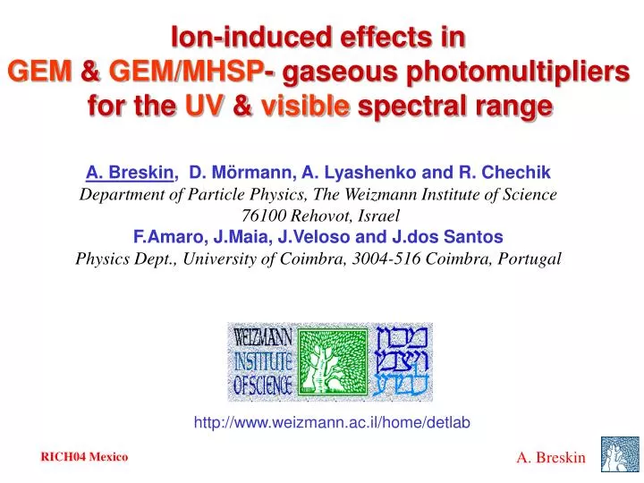
Ion-induced effects in GEM & GEM/MHSP - gaseous photomultipliers for the UV & visible spectral range. A. Breskin , D. Mörmann, A. Lyashenko and R. Chechik Department of Particle Physics, The Weizmann Institute of Science 76100 Rehovot, Israel

E N D
Ion-induced effects in GEM & GEM/MHSP- gaseous photomultipliers for the UV & visible spectral range A. Breskin, D. Mörmann, A. Lyashenko and R. Chechik Department of Particle Physics, The Weizmann Institute of Science 76100 Rehovot, Israel F.Amaro, J.Maia, J.Veloso and J.dos Santos Physics Dept., University of Coimbra, 3004-516 Coimbra, Portugal http://www.weizmann.ac.il/home/detlab
photocathode CsI on readout pads Gaseous Photomultipliers (GPM) Gas 1 atm (F.Piuz et al) Possible solution: closed geometry Cascaded GEM & others • Problems with wire chambers: • open geometry • Photon and ion feedback • gain limitations • - Damage to the photocathode I will discuss only our work!
Multi-GEM GPM Semitransparent Photocathode Reflective Photocathode higher QE! • largely reduced photon feedback compared to “open” geometry •no photon feedback • thick pc: easier production • low sensitivity to charged particles! A. Buzulutskov et al. NIM A 443 (2000)164 D. Mörmann et al. NIM A 478 (2002) 230 • high 2D precision [0.1-0.2 mm] • high gain [>105] single photon sensitivity! • fast signals [ns] good timing
Multiplication in multi-GEM structures D. Mörmann et al. WIS For a given total gain: a larger number of GEMs permits operation @ lower V GEM HIGHER STABILITY
high DVGEM high surface field low backscattering E drift E GEM Electron transmission into holes VGEM=100V VGEM=300V VGEM=500V E>2 0.7 1.0 1.4 1.9 2.6 3.7 5.2 7.3 10 14 20kV/cm Good extraction => optimal operation at high DVGEM
Refl. CsI, 1 atm CF4 3 GEM, single electron pulses. e- 50mV 10ns gain 105, no photon feedback. GPMs: highlights With reflective PC: low sensitivity to ionizing background radiation - Reflective PC (compared to ST), higher QE, low sensitivity to ionizing BG radiation - High optical opacity of multi-GEM, no photon-feedback - Reduced ion back-flow (compared to MWPC) - Reduced secondary effects high gains 106 - 107 - Operation with large variety of gases, noble gases, CF4, etc - Fast: with CF4s= 1.6ns w\single electrons s=0.33ns w\150 electrons
GPM LXe Examples of GEM-GPM applications • Hadron-Blind Detector (HBD) for PHENIX (I.Tserruya et al. Weizmann) • UV imaging detectors of LXe scintillators for Dark-Matter experiments (XENON, E. Aprile et al. Columbia Univ.) • UV imaging detectors for a fast LXe Gamma-camera for PET ) D. Thers - Nantes/A.B.-Weizmann) Xe GAS LIQUID Xe
Visible-range Gaseous Photomultipliers UV: established technique various ~“air-stable” photocathodes Real challenge: GPMTs for the visible range! Photocathodes(e.g. bi-alkali) are very chemically reactive. Cannot operate in flow-mode! Solution: Visible-range GPMTs => sealed mode visible UV D. Mörmann et al. NIM A504 (2003) 93
Sealed detector package with semitransparent K-Cs-Sb PC ~2” 13% = best QE measured after sealing. 2 weeks stability 15 10 Q E % 300 400 500 600 Best sealed GPMT: QE = 6% @ 365nm stable for 1 month 5 QE in transmissive mode Ar / CH 4 95 / 5 % Wavelength [nm] GPMT for visible light sealed 3 Kapton-GEMs & KCsSb PC Sealing in gas: In/Sn; 130-1500C QE in Ar/CH4 (95/5) ~ 70% of QE in vacuum (backscattering) best expected ~20% @360-400 nm under development: Silicon, ceramic Expected higher stability D. Mörmann et al. NIM A504 (2003) 93 M.Balcerzyk et al. IEEE TNS 50 (2003) 847
100mV/div 400ms/div Gain limitation by ion-feedback No significant feedback observed with CsI Significant with efficient secondary electron emitters, e.g. visible photocathodes K-Cs-Sb: Current deviates from exponential 1 atm Ar, 1 GEM ST PC Ion feedback: photocathode-dependent (band gap, electron affinity) gas-dependent (ion species, PC surface processes) field-dependent (ion velocity) Recently measured: SEE Probability = 0.05 – 0.5 electron/ion in Ar/CH4 mixtures (Gas dependent, Ar is worst)
Secondary avalanches due to ion feedback gain limits, imaging problems (observed in K-Cs-Sb) Photocathode damage due to ion sputtering observed in both: CsI and K-Cs-Sb Major efforts to limit ion backflow Drawbacks of ion-photocathode interaction
Ion back-flow in multi-GEM Tracking detectors & TPCs Back-flowing ions Distort the E-field Ed Electron’s path Ion’s back-flow Ed can be kept relatively LOW reduces ion back flow to a few % levels Ed cannot be too low keep e-diffusion low localization resolution S.Bachman et al. NIMA438(99)376: 5% @ 0.5kV/cm A.Breskin et al. NIM A478(2002)2252-5%@ 0.5kV/cm A.Bondar et al. NIM A496(2003)3253%@ 0.5; 0.5% @ 0.1 kV/cm (GEMs with small holes)
Ion back-flow in multi-GEM Detectors with solid converters Electron’s path Ion’s back-flow - • Attempts to reduce the ion back-flow: variables DVGEM ; Etrans ; Eind • E@ photocathodemust be high for good e-extraction; best @ high VGEM • Ion back-flow 10-20% at best…! (without affecting e- transfer) D. Mörmann et al. NIM A516 (2004) 315
The Microhole & Strip Plate (MHSP) Two multiplication stages on a single, double-sided, foil J.M.Maia et al. IEEE NS49 (2002) J.M.Maia et al. NIM A504(2003)364 • Foil:5 mm copper on both sides of 50 mm Kapton • Bi-conical holes: 50/70mm (inner/outer) diameter • Anode-strip pattern:175 mm pitch /15 mm strips • Production: similar to GEM technology (CERN) R&D in course: Weizmann/Coimbra
Ion back-flow: MHSP vs GEM J.Maia et al. NIM A523(2004)334 Multi-GEM GEM & MHSP A C anode bottom cathode All ions flow back Some ions flow back but others flow towards the strip cathodes and bottom cathode GEM & MHSP: ion flow reduced to 2-3% levels!
hv photocathode E drift VA-C VC-T C A E trans cathode mesh MHSP simulation Simulations:Oleg Bouianov
1 V =350 V 315 V GEM1 V GEM3 V =V 280 V GEM2 GEM3 ð E =1.0 kV/cm T1 E =E =0.25 kV/cm T2 T3 Ion back-flow ratio 0.1 250 V 2 - 3% V E =- 5.0 kV/cm 300 V hole ind 350 V Ar/5%CH p=760 Torr 4 0.01 1E+02 1E+03 1E+04 1E+05 1E+06 Effective Gain The multi-GEM & MHSP photomultiplier J. Maia et al. NIM A523(2004)334 1 V =350 V 315 V GEM1 V GEM3 V =V 280 V GEM2 GEM3 H E =1.0 kV/cm T1 E =E =0.25 kV/cm T2 T3 Ion back-flow ratio 0.1 250 V 2 - 3% V E =- 5.0 kV/cm 300 V hole ind 350 V Ar/5%CH p=760 Torr High gain and low ion back flow: 2-3% 4 0.01 1E+02 1E+03 1E+04 1E+05 1E+06 Effective Gain
Ion back-flow reduction: reversed-MHSP & GEM J.Veloso et al. WIS/Coimbra IEEE 2004 MHSP: gain & ion blocking R-MHSP: ion defocusing* * R-MHSP: Roth, Vienna 04 R-MHSP Gain=30 ~300 ions/e A C 30 x gain 4 x ions! ~1200 ions/e MHSP A C WIS/Coimbra 10-3 R-MHSP A C + IBF: Ion Backflow Reduction IBF R&D IN PROGRESS!
Other ion-suppression ideas Gain of 1st element: 20-30
Ion backflow (reflective photocathode) Gain of R-MHSP1 ~ 30
Feedback pulses Ion Gating E1 E2 1. Gate open => electron transfer 2. Gate closed, after electron transfer, => ions are stopped 10-4 Non-gated GEM: at best 10% ion-feedback Gated GEM: ion suppression to 10-4levels! Problem: dead time! (ms) D. Mörmann et al. NIM A516 (2004) 315
>105 Gated GPMT for visible light GAIN: 100-1000 in DC mode (ion feedback limit) >105 in ion-gating mode A breakthrough! D. Mörmann et al. WIS 2004
At gain ~ 105 Multi-GEM: IBF = 10-1 – 2 10-1 Multi-GEM & MHSP: IBF = 2 10-2 Multi-GEM & MHSP & R-MHSP: IBF = 1-3 10-3 Gated multi-GEMs: IBF = 10-4 Ion-suppression: summary Photocathode life-time, TPC ,depends on the total ion’s accumulated charge on the photocathode: TPC (GEM-like GPM) = TPC(MWPC GPM) x1/IBF Operate at minimal possible gain!
K-Sb-Cs photocathode ageing Aging of K-Cs-Sb under avalanche-ion bombardment in Ar-CH4(5%) CsI KCsSb 4-GEM / semitransparent photocathode a small fraction of ions hit the pc slow aging CsBr parallel-grids / semitrans. photocathode all ions hit the pc faster aging!
GEM photomultipliers (GPM): - a mature concept in the UV - important progress in the visible Other advanced “hole-multipliers”: MHSP, TGEM(talk by Rachel Chechik) Ion blocking: cascaded GEM/MHSP/RMHSP – 10-3 importat also for TPCs! Summary
HV 20kV Xenon gas GPM Cathode wire plane Thermal Screen PTFE Wall 9 cm LXe Metallic Micromesh HV [1-2] kV Liquid Xenon Anode plane 511 keV Gamma ray SiO2 entrance window (3mm) LXe-gaseous PMT gamma-camera for PET SUBATECH-Nantes/WEIZMANN
Suggested GEM in the XENON Detector The XENON Dark Matter search: E. Aprile et al. Columbia Univ. astro-ph/0207670 1 ton liquid Xe detector with multi-GEM GAS PHOTOMULTIPLIER Xe GAS Replace LIQUIDXe Primary scintillation: Photo-effect in LIQUID & GAS Secondary scintillation: Induced by electrons extracted from LIQUID & drifting in GAS WIMPS
Suggested PHENIX HBD e- Simulation Real life…. HBD A single event recorded in the STAR TPC showing hundreds of particles: most of them HADRONS A single 100 MeV electron identified by a “Cerenkov signal” in the HBD GEM-photodetectorinsensitive to particles!
TPC/HBD for RHIC-PHENIX I. Tserruya et al, WIS Large area UV detector 3-GEM/CsI TPC Readout Plane Drift regions HV plane (~ -30kV) Readout Pads DR ~ 1 cm f ~ 2 mm Grid GOAL: identification of a few low-mass e-pairs out of hundreds of Hadrons / collision
Ion feedback to the ST photocathode GPM TPC Ion feedback as a function of the drift field 1% “standard” GEMs Breskin et al. NIM A478(2002)225 Dependence on the gain: 3GEM vs 4GEM Bondar et al NIMA A496(2003)325 Breskin et al. NIM A478(2002)225 Factor 2-3 IBF reduction 5%
Variable:GEM voltage Variable:Induction field 20% 10% at best Ion back-flow in multi-GEM with reflective pc D. Mörmann et al. NIM A516 (2004) 315 Variable:transfer field 20%