Download
1 / 34
340 likes | 482 Views
The BaBar LST detector High Voltage system Design and implementation. Gabriele Benelli K.Honscheid, E.A. Lewis, J.J.Regensburger, D.S. Smith The Ohio State University. Outline. HV requirements Design Features Controls and running experience Summary and conclusion. The BaBar LST detector.

E N D
The BaBar LST detector High Voltage systemDesign and implementation Gabriele Benelli K.Honscheid, E.A. Lewis, J.J.Regensburger, D.S. Smith The Ohio State University
Outline • HV requirements • Design • Features • Controls and running experience • Summary and conclusion
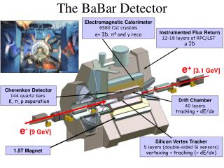
The BaBar LST detector • Limited Streamer Tubes (LSTs) chosen to replace the rapidly ageing Resistive Plate Chambers (RPCs) in the BaBar Instrumented Flux Return (IFR) as muon detectors • BaBar LSTs: • Tubes with 7 or 8 wires (cells) coupled in 4 HV channels • Active region between 5 and 6 kV • Readout signals AC coupled to HV channels
Plateau BaBar LST HV requirements • Very high granularity: 1164 tubes->4656 HV channels • HV operating point affects efficiency and currents • Radial distribution of LSTs in 12 layers of 20 tubes or less: • Tubes in layers closer to the interaction point draw more current • Losing one layer for a short time does not affect data quality • No need for individual tube HV control • High luminosity or background conditions may require to operate the inner layers tubes at a lower working point 12 LST layers +6 absorber layers per sextant 4656 individual HV lines and current monitors VERY EXPENSIVE BUT Current increases All tubes in a layer can share HV Single layer does not affect global efficiency
BaBar LST HV • Typical currents at 5.5kV per tube: • No beam 15-100nA • With beam 50-1000nA • Self-discharge mode: • Current rises up quickly to over 3000nA due to one single HV output • Monitoring current for whole tube (4 HV outputs) is sufficient: • Built-in flexibility to disconnect individual HV outputs and treat separately • Overcurrent protection for self-discharge mode • Trip logic
OSU HVPS features • 320 HV outputs • Variable output voltage 0-6kV • 4 independent HV groups of 80 HV outputs at same voltage setting • 80 current measurement channels • 4 paralleled HV outputs per channel • Add picture of back panel (This one for now, add animation or pointers for 1 tube->4 pins, 20 chs->1 HV grp)
OSU HVPS ingredients • Rabbit microcontroller • Xilinx FPGA (data collection and control signal generation) • Ultravolt DC-DC converter (internal HV power supply) • 4 variable HV regulators • 80 current measurement modules • 320 2mm banana plugs connectors (+ grounds)
Current monitor module • 0-12 μA current measurement with 1nA resolution • Floating power supply referenced to the module output voltage: • Operation at any output voltage • Floating circuitry survives unexpected output transients • Low power ADC circuit using a voltage controlled oscillator (VCO) • VCO frequency transformer coupled to low voltage for counting • Frequency readout by Xilinx FPGA • Output overcurrent protection
Current monitor diagram Floating +5V (DC) power supply + VCO clock Low Voltage High Voltage Output current ADC To Xilinx Sense resistor Voltage to frequency High Voltage Low Voltage Voltage buffer
Overcurrent protection • Based on the LST principle of operation: • Typical operational currents are small • Self-discharging mode causes high currents (>2.5μA) • Discharge stops when voltage drops below LST active region • Overcurrent protection threshold: Ithreshold = (VBRICK - HV SET)/500MOhm • Software Adjustable (via VBRICK) IThres= 3μA VBRICK = 7kV Normal Operation Self Discharge Larger current If current demand increases output voltage drops linearly Current larger than overcurrent threshold IThres= 2μA Small current to output Self-discharge stops Forward bias Reverse bias Tube automatically recovers VBRICK = 6.5kV
Voltage regulation • Internal Ultravolt DC-DC converter (0-10kV at 3mA) • 4 independent HV group voltages set by 12-bit DACs through Xilinx FPGA • HV group output voltage measured by VCO ADC circuit Feedback High Output Voltage Low Output Voltage Voltage measurement Low BJT Current High BJT Current HV BJT
Digital Board/Firmware • Rabbit RCM-3200 microcontroller with Dynamic C embedded software: • Monitoring and control algorithms • Ramping and trip logic • Detector controls integration • FPGA (low level logic and signal conditioning): Xilinx Spartan XCS-30 • Input/Output through Ethernet or CANbus [ADD PIC OF DIGITAL BOARD]
Built-in Ramping and Trip Logic • Configurable ramping logic: • Separate ramp up and ramp down speeds • Intelligent ramping (regulate speed to prevent spike trips from charging currents) • Sophisticated trip logic: • Spike trip • Time over threshold trip: • Individual channel trip level • Individual HV group trip time • Ramping and stable HV trip level and trip time • Internal power supply trip • Diagnostic: • CANbus and Ethernet: • Status reporting • Ad hoc diagnostic • Rabbit Serial output: • Operation log and debug diagnostic
Detector Controls • Qt standalone Ethernet GUI • BaBar slow controls integration: • MVME5500 IOC, running RTEMS • EPICS detector control software: • State machine sequencers, controls and panels • Alarm handler • Database archiving
QC and beam experience • 25 HVPS have been built: • 18 will power the LST detector • 3 will be “hospital” supplies • 4 spares • 23 HVPS currently at SLAC: • 6+2 used in BaBar to power top and bottom sextants • 15 used for QC and conditioning of the remaining uninstalled sextants • They were used for QC (now complete) • ….
Luminosity driven operational change • Beam experience: • Innermost layers tubes drew high currents as a function of luminosity • First two layers tubes were split into two HVPS channels • Extrapolating to higher luminosity shows the overcurrent protection threshold in the HVPS needs to be increased Estimate for 2x10^34 luminosity is 8000 nA per tube Layer 1 (SPLIT) total current Layer 2 (SPLIT) total current Current (nA) With a firmware upgrade, already planned, the LST HVPS will be able to power the inner tubes in this scenario Layer 3 total current Layer 4 total current Layer 6 total current An advantage of a flexible custom HV system! Luminosity (x1033cm-2s-1)
Summary and conclusions • The OSU HV system provides the BaBar LST detector with a versatile and robust solution • Excellent performance and flexibility experienced during QC and data-taking • Ready for the rest of the LST installation in Summer 2006
BACK-UP SLIDES • BACK-UP SLIDES
The BaBar LST detector • BaBar Limited Streamer Tubes (LSTs): • Tubes with 7 or 8 wires (cells) • Cells are (1.75x1.75)cm2 and 358cm long • Wires coupled in 4 HV channels per tube • The 4 HV channels are readout channels • Operated at 5500V, with Ar/Iso/CO2 gas mixture (3%/8%/89%) • Z-strips: • Vacuum laminated Cu-foil + Mylar • 96 strips (orthogonal to LST wires) • 35mm wide strips separated by 2mm gap • LSTs were installed in summer 2004 in the IFR top and bottom sextants: • 12 active LST layers per sextant • 6 layers of brass per sextant
Wires HV connectors Granularity • Very high granularity: 1164 tubes->4656 HV channels
OSU HVPS features • Variable output voltage 0-6kV • 320 HV outputs • Channels are grouped into 4 HV groups of 20 channels each • Current measurement resolution 1 nA (0-12μA) • Voltage measurement resolution 1V (1-6kV) • Individual channel overcurrent protection • Ramping and trip logic • Ethernet and CANbus communication protocol
Single Rates • Tubes are tested by scanning their counting rates at several HV points (single rate measurement): • Single rates measurements are done once a month • All tubes show nice plateaus Plateau
LST radiography LST Layers Top Wire holders Bottom
LST Muon ID Performance • Pion rejection vs. Muon efficiency for high and low momentum muons LSTs RPCs
Rabbit/Xilinx/Boards/Interlocks • Microcontroller Rabbit (Ethernet port) RCM-3200 • FPGA Xilinx Spartan XCS-30 • Dynamic C embedded software developed • I/O: • Ethernet • CANbus controller Philips SJAXXXX • Front panel interlocks: • HV external enable signal • HV enable switch • Injectable voltage • Trip • Ramping • Go to Injectable voltage • LEDs: • HV on for each HV group • Ramping, trip, Injectable, etc
Detector controls Features • Injectable/Runnable • Alarm Handler • Ambient DB and Archiver • Save restore • Trip reporting • Automated Trip reset • Single Rate • Conditioning
The LST HV system • OSU HVPS: • Run5: 6 HVPS + 1 hospital supply • HV output up to 6000V • 80 current monitoring channels • 4 HV output pins per channel (corresponding to a tube) • High granularity (320 outputs) • 4 HV groups of 20 channels (corresponding to a layer) • Safe for detector: • Individual channel LST overcurrent protection • Sophisticated trip logic (spike, time over threshold, ramping, internal power supply) • HV control box to provide input to BaBar SIAM injection inhibit • Safe for operations: • Removable key • External signal/front panel/software HV enables • Highest output current per channel 12 microAmps (startle hazard) • Fully integrated (via CANbus) in BaBar ODC and state machine • Easy access for maintenance • Upgradeable firmware to implement new features
LST HV system • Run5 LST HV system performance was fine • Beam experience: • Some wire channels showed a repetitive trip behavior and the hospital HVPS helped recover some of these channels. Problematic channels are operated at lower voltage • Frequency of trips of LSTs due to self-sustained discharge at higher luminosity suggests the implementation of an automatic trip reset functionality • A few problems: • 2 HVPS failed (with a known failure mode) in IR2 and they were replaced • LST SIAM injection inhibit signal glitch due to a firmware bug, it was solved with a firmware upgrade • All 23 LST HVPS (21+2 spares needed for final configuration) are at SLAC and are working fine: • 7 HVPS in IR2 power top and bottom sextant (including hospital) • 1 extra spare ready in IR2 • 13 HVPS powering tubes in CEH and gaining operational experience • 2 extra spares in CEH
The LST slow controls • IOCs: • ifr-mon, ifr-hv, lst-hv • All running VxWorks and EPICS 3.14.7 (CBlow task patch is in) • Using lst-test in CEH (controlling 15 supplies and 1 GMB): • PPC IOC • RTEMS operating system • EPICS 3.14.7 • Status: • All IOCs running smoothly • ODC: • The first deployment of a PPC/RTEMS IOC in IR2 (in June) caused communication problems (and some down time, half of the time listed in Steve’s wall of shame for LSTs) • After a quick revert to the MVME/VxWorks old solution, no LST IOC crashes experienced. • A few new features/utilities introduced for operations: • Configuration tools • Automatic trip logging/reporting/paging
LST Event Display • Di-muon event in the LSTs
CEH status • AllLST modules, cables and HVPS are at SLAC: • All HVPSes, long- and short-haul cables working fine and being used • Finished QC on all LST modules (many man-years effort, thanks to the CEH shifters crew!) • QC data analysis in progress, already plenty of good modules for next installation • Operations: • Keep all tubes under gas and HV • Opportunity of shift sign-up for next summer installation