Download
1 / 10
100 likes | 241 Views
The (prototype) C&V Framework component used for the SPD Cooling Control. A.Tauro, G.De Cataldo. The SPD cooling system. Pumps perfluorobutane (C 4 F 10 ) in the SPD cooling circuits Evaporation of C 4 F 10 at approximately 15ºC Vapor drawn back by a membrane compressor

E N D
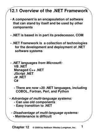
The (prototype) C&V Framework component used for the SPD Cooling Control A.Tauro, G.De Cataldo
The SPD cooling system • Pumps perfluorobutane (C4F10) in the SPD cooling circuits • Evaporation of C4F10 at approximately 15ºC • Vapor drawn back by a membrane compressor • Condensation by means of a constant supply of chilled water • Cooling power of approximately 3kW, distributed over 10 loops
The SPD cooling system control • The process of the SPD cooling system is controlled by a dedicated Schneider PLC • Process Control: • Common outlet pressure controlled by the liquid pump speed • Common inlet pressure controlled by the compressor speed • Operating cycle (Stop, Stand-By, Run end Recovery) • General System Status (Alarm and Warning) • Distribution Control: • the PLC doesn’t control the distribution lines except the OPENED-CLOSED-LOCKED status of each loop.
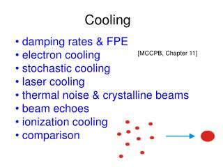
The cooling plant • Although the cooling plant in the figure is the one for the HMPID, it looks like the one of the SDD. This is of help to describe its main parts and related functions: • the rack on the left contains pumps, the cooling liquid, heat exchanger, loop connection and all the relevant actuator to monitor and control the hardware; • On the left rack are located respectively: • The local operator panel that allows for a full monitoring and plant control; • The Schneider PLC; • The cable connector.
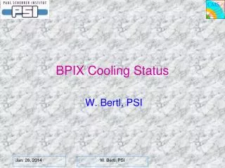
TS/CV SCADA CCC MODBUS TCP/IP Final communication scheme Actual communication scheme TS/CV SCADA CCC = CERN Control Center TIM=Technical Installation Monitory DSS= Detector Safety System TS/CV SCADA TIM CCC TIM ALICE DCS& detector DCS Gateway PLC Gateway PLC Available Digital programmable I/O (ex: relays for Interlocks) MODBUS TCP/IP Process PLC Process PLC Alice HMPID SPD In order to safely manage the communication between all the process PLCs of the ALICE experiment and the technical network, the TS/CV/DC group will install the Gateway PLCin the experimental cavern.
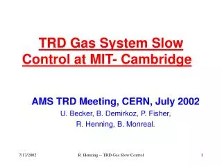
DCS cooling The FSMs of the SPD cooling plant and their integration in the DCS Operating cycle General System Status STOP STAND-BY OK Severe alarm condition Automatic recovering when the warning is over Exit on local RESET RECOVERY RUN WARNING ALARM • During the pre-installation phase, it is under the responsibility of each sub-detector to integrate the cooling FSMs in the DCS. A possible hierarchy is presented in figure. Details can be discussed case by case. • In the ACC is under way the discussion of a project integrating, after the pre-installation phase, all the ALICE cooling plants in a unique control system.
The prototype of the C&V FW Component • PVSS 3.01 SP1 • fwCoolingAndVentilation 0.14: • This tool is not yet official. The official version will be released in the next months after the collection of the comments and suggestion from the 4 LHC experiments • SCY file (20-01-06) for the SPD: • ready for the gateway PLC • The time schedule for delivering to others sub-detectors the updated SCY file is not jet available, but it is under discussion in the ST/CV group. For the HMPID it is foreseen not before the end of march.
The synoptic panel of the SPD cooling plant Each sub-detector has to provide a similar synoptic panel with the representation of the cooling system and possibly the detector. It can be integrated either in the FW component either in the monitoring zone of the FSM control panel (see the presentation on:Standardization of the DCS control panels)
Conclusions • The FW component and the updated SCY file (provided by the TS/CV group) have been successfully tested with the SPD cooling plant; • For the HMPID the SCY file will be released not before the end of march 06, and for the remaining cooling plants the schedule is being studied; • During the pre-installation, the cooling plant control has to be done at level of single sub-detector; therefore the corresponding cooling FSM has to be integrated in each DCS. • Each sub-detector has to prepare a synoptic panel with the representation of the cooling system and possibly the detector. This panel can be used in both the FW component and in the FSM control panel.