Lead
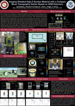
Imaging Shielded High-Z Nuclear Material with a Compact Muon Tomography Station Based on GEM Detectors M. Hohlmann , V. Bhopatkar, M. Phipps, M. J. Staib, J. Twigger, C. Zelenka Dept. of Physics and Space Sciences, Florida Institute of Technology, Melbourne, FL 32901, USA. Abstract.

Lead
E N D
Presentation Transcript
Imaging Shielded High-Z Nuclear Material with a Compact Muon Tomography Station Based on GEM Detectors M. Hohlmann, V. Bhopatkar, M. Phipps, M. J. Staib, J. Twigger, C. Zelenka Dept. of Physics and Space Sciences, Florida Institute of Technology, Melbourne, FL 32901, USA Abstract Muon Tomography Concept Incoming muons (from natural cosmic rays) Muon tomography aims at detecting and 3D-imaging well-shielded high-Z material, e.g. nuclear contraband in cargo, for homeland security and other applications. This zero-dose technique exploits multiple scattering of atmospheric cosmic ray muons, which is larger in dense, high-Z nuclear materials than in low-Z and medium-Z shielding materials. We are operating a compact Muon Tomography Station that tracks muons using 30cm × 30cm Triple Gas Electron Multiplier (GEM) detectors with 2D readout placed on four sides of a 27-liter cubic imaging volume. Data from ~12,000 strips are acquired with an RD51 Scalable Readout System. We present experimental performance of this station, specifically the imaging performance for shielded uranium. With typically 100k reconstructed muon tracks, the station can resolve the gap between two high-Z objects placed at least 6mm apart in the horizontal plane. It images a 75cc depleted uranium cube shielded on all sides by ~2cm thick medium-Z bronze material. The same cube can be imaged through vertical clutter of 12cm of low-Z steel shielding. Sizes and 3D shapes of metallic objects with dimensions of a few cm that are shielded by a lead box with 3.4mm walls on all sides have been reconstructed successfully. Using the observed scattering signatures, these shielded objects can be distinguished from each other according to their radiation lengths including clearly distinguishing uranium from lead. A scaled-up muon tomography station with 0.5-1 cubic meter active volume will use compact tracking stations with large-area GEM detectors in the future. μ μ Uranium Iron μ μ Fe U Small Scattering Large Scattering Small Scattering Large Scattering Note: Angles Exaggerated! Tracking Detectors Main Idea: Multiple Coulomb scattering is proportional to atomic number Z, allowing for discrimination of materials by Z. Muon Tomograms of Various Shielded Target Scenarios 27-lit. Muon Tomography Station with 8 GEMs Point-of-Closest-Approach scattering reconstruction Multiple projections of materials shielded by 3.4 mm lead box Prototype muon tomography station designed and built at Florida Tech. The design allows for adjustable station configurations including side detectors. The current configuration includes 8 triple-GEM detectors (yellow) surrounding four sides of a 1ft3 (27 l) active volume. XZ Slices Tantalum A at Y = 70 mm Slices W Pb Ta Tungsten Lead placed inside Tin Uranium Iron at Y = 0 mm Object U Scattering angle: XY Slice Z = 20 mm X = -70 mm X = 0 mm X = 50 mm YZ Slices B Pb U Sn Fe W at Y = -60 mm Pb Ta Uranium shielded by 2 cm of Lead Sn Fe Triple-GEM Detectors XY Slice 335k reconstructed events; # neighboring POCA Cut = 5 U XY Slice Z = -60 mm Triple-GEM Detector instrumented with 12 APV25 hybrid cards (SSD = sum of all scattering angles within target volume per 1000 tracks) Ta Pb W 3.4 mm top lead 10 mm top lead Data fitted to 1/X0 U Fe Sn 380k reconstructed events with # neighboring POCA Cut = 5 YZ Slice X = -20 mm DAQ Hardware & Software Typical Integration times for all these scenarios: 24-48 hrs. The >12k analog channels are digitized at 40MHz and read out at ~35 Hz using the largest implementation of the RD51 Scalable Readout System (SRS) to-date. The SRS was developed at CERN as a low–cost scalable DAQ system for specific use with micropattern gaseous detectors. Data are collected using a hybrid card based on the 128-channel APV25 chip and sent via HDMI cables to ADC cards which support 16 APV hybrids each. ADC data are formatted by a front end concentrator (FEC) based on the Virtex LX50T FPGA. Data from 6 FECs are sent via gigabit ethernet through two switches to a DAQ computer at 15 MB/s and processed for online and offline analysis using DATE and AMORE DAQ software developed for the ALICE experiment. Raw event size without zero suppression is ~500 kB. Uranium Shielded by 1.7cm of Bronze 3 Lead-Acid Batteries Impact of Side Detectors - XY Plane Top/Bottom Detectors only XY Slice at Z = -70 mm 159,955 reconstructed tracks # neighboring POCA Cut = 5 Top/Bottom & Side Detectors XZ Slice at Y = 0 mm Tests relative acceptance within probing volume and the effect from tracks through side detectors (in particular near the edges of the volume) 260k reconstructed events # neighboring POCA cut = 5 APV25 Hybrid Card (RD 51 series production) Future Work Image Resolution Achieved: ~6 mm horizontal & ~45 mm vertical Horizontal Scenario Vertical Scenario We plan to improve the track reconstruction further, e.g. by including additional detector layers and more robust hit and track selection algorithms to reduce the number of improperly assigned tracks. The alignment can be improved by taking relative detector rotations into account in addition to the currently implemented relative shifts. There is also a need to suppress zeroes in the data at the DAQ firmware level to reduce the overall raw data size and speed up data processing. We anticipate the construction of a larger MTS prototype with 1m3 volume using 1m long GEM chambers similar to those that have been developed recently by the CMS GEM and RD51 collaborations and use of time-of-flight information. 0mm gap 8mm gap 15 mm gap 45 mm gap 45mm gap (reversed) 2 mm increments Lead Lead Tungsten 15 mm increments Switch target positions Lead Tungsten Lead Tungsten y Tungsten Tungsten x Lead Acknowledgments & Disclaimer 4 mm horizontal gap 6 mm horizontal gap 8 mm horizontal gap 15 mm vertical gap 45 mm vertical gap 45 mm vertical gap We thank the RD51 collaboration and the GDD at CERN for their extensive technical support. This material is based upon work previously supported in part by the U.S. Department of Homeland Security under Grant Award Number 2007-DN-077-ER0006-02. The views and conclusions presented here are those of the authors and should not be interpreted as necessarily representing the official policies, either expressed or implied, of the U.S. Department of Homeland Security.