Software Engineering Design Analysis
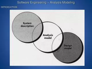
Software Engineering Design Analysis. Chapter 7. Software Engineering Design Analysis. software engineering design. Goal of engineering design analysis is to understand the software product design and the constraints (from requirements)

Software Engineering Design Analysis
E N D
Presentation Transcript
Software Engineering Design Analysis Chapter 7
Software Engineering Design Analysis software engineering design • Goal of engineering designanalysisis to understand the software product design and the constraints (from requirements) • The Engineering DesignAnalysis consist of 2 maintasks • Understanding(studying, clarifying, prioritizing, etc.) the SRS and product design • Developinga “new” model of the design problem • The result of design analysis “often” requires further clarification and rework of the SRS and product model SRS/Product Design Analyze (SRS & Product Design) Perform Rest of Design Steps Design Doc Recall Product Design is really requirements (your text author)
Engineering Design Analysis • Engineering Design Analysis Model is a representation of a design “problem” (the modeling of the issues related to requirements) • Dynamic aspects may be represented with Use Case Diagram and Use Case Description which • Defines the major system functionalities • Defines the entities or actors (mostly users and other systems) that interact with the system • Describes the actual interactions via scenario descriptions • Static aspects may be represented with Conceptual Model (or Analysis Class Model if using OO). (Using OO techniques) • Defines the “Classes” in the problem 2. Defines the Associationsamong Classes Note: Both Use Case Diagram/Descriptions and Conceptual Model (OO Class Diagram) may be used for both requirementsand designactivities
Use Case: Represents the requirements and the behavior of the needed system Does not describe the solution ‘Usually” does not describe in detail the entities or the structure in the problem/solution (does describe interactions between actors and the system) Conceptual Model: Also represents the problem/solution, the static aspects Does not “quite” describe the solution, but starts to Does describe (more details of) the real world and possible artificial entities relationships among these entities Use Case and Conceptual Model
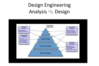
3 Levels of Model in Analysis and Design OO Model • Conceptual Model (or Domain Model) :represents the entitiesin the problem domain-a) their characteristics, and b) relationships among the entities (the entities may be represented in the form of OO classes) • Design Class Model: represents the entities in the solution –a) their attributes, b) operations, and c) relationships among the entities independent of the implementation language or platform • Implementation Class Model: represents the classes in the implementation of the solutionand all the details which were left out in the Design Class Model OO Code
Conceptual Model • Conceptual model is the “bridge” between requirements (problem) and design (solution). • Conceptual Modeling is used for Analysis of “mostly” requirements: • Understanding the problem domain: • the major entities, • the responsibilities (or functionalities) of these entities, • and the relationships among these entities • Understanding the data requirements that are associated with entities, their characteristics, and their relationships - - - - - - - - - - - - - - - - - - - - • Reviewing/Inspection of the SRS against the Conceptual Model With a Conceptual Model, many of the entities, characteristics, responsibilities, and relationships that are portrayed in the problem domain may be transformed into classes, attributes, operations, and associations in the Design Model
RESPONSIBILITY-DRIVEN DESIGN [Wirfs-Brock et al., original work in 1990] • Design technique driven by the delegation of responsibilities • Goal -- To focus on building a model of interacting objects before filling out precise details of each class • Involves reducing data & control dependencies between modules (information hiding) and designing reusable code • Philosophy -- No action can take place without an agent (object) performing the action. • Central focus of OOD -- establishing WHO is responsible for each action
CRC Cards • Using CRC cards is a popular approach that works with Responsibility-Driven Design to help identify the “key” components of the problem arena. • CRC cards: Class, Responsibility, & Collaboration • An object’s responsibilities are high-level statements about the knowledge it maintains and the operations it supports • A collaboration is a request made by one object to another • Each class = a CRC card • C : Class (“key” component) • R : Responsibility (functionality/feature) • C : Collaboration (interfaces with other Classes)
class name ______________________________________________ [subclass: ] [superclass: ] responsibilities collaborators CRC cards show the identifiedEntities/Classes These are found in requirements(from Use Case)are often“directly” converted toClasses to be used in the Design
So --- How do we come up with an entity (CLASS)? • A CLASS is an abstraction of an entity in requirements at this stage. • The entity may be a “real” physical world item described in the requirements document (e.g.) • “A patient form must be filled by each patient” ---- (in describing the requirements for a hospital admittance process.) • The entity may be a conceptual (man-made)item described in the requirements (e.g.) • “When the patient’s accrued backlog payment amount is more than $10,000, a statement of possible financing alternatives is included in the financial invoice statement to the patient” ---- (in describing the billing statement of a hospital system) (note that financial invoice statement may be verbal, electronic, or paper in form; but it is not a “real” world item.) At the Conceptual Design level, we are dealing with requirements/design. Thus the “major entities” mentioned in the requirements document are candidates for CLASSES. CLASSES may have to be defined and alteredseveral times in Conceptual Design and even in the later Design Class Model !
Identifying Key Components • Identifying key components or Classes is the first step. • Just “listing” the Classes’ names (no other information about the Classes, yet) • After thinking about what functionalities (or responsibilities) these Classes should possess ----- (we may actually change our minds and combine some Classes ---- we now are starting to drop into“Designing Class Model”) • We may start to associate Classes in terms of relationships
CLASS Representation in UML • A Class is composed of 3 parts: • Class name • character string that identifies the Class • Class attributes • list of characteristics of the Class that are eventually stored in “variables” and “constants” • Class operations • list of services or functionalities provided by the Class Patient P_Name: string [1.. 40] P_Address: string [1..50] P_Phone: string [1..10] P_Age: int . Get_P_Name( ): string Get_P_Addres( ): string Input_P_Name ( ) . . 1) Coming up with CLASS is an important and difficult design task!!! 2) At this point, don’t get too tangled up in the details.)
Class Attribute Specification Format • name : type [multiplicity ] = initial value • name : a “simple” name to identify the attribute; • type: name of the data type or class type; • multiplicity: the number of values stored in the attribute; • initial value: initial value assigned to the attribute; • Some notes: - • at the analysis level, we will ONLY have the NAME • multiplicity may be comma separated list of ranges of non-negativenumbers, where each range is in the form of j---k (e.g. 1---6) • * stands for unlimited upper bound 0---* mean 0 or more • if multiplicity is suppressed, it is assumed to be 1 and the [ ] may be dropped
Class Operations Specification • name ( parameter-list ) : return-type-list • name : a “simple” name of the operation • parameter list: a comma separated list of names and types of the parameters of this operation in the form of : direction param-name : param-type = default value • direction is either in, out, inout, return ; if suppressed it is assumed to be in • param-name is the simple name of the parameter • param-type is the data type or class of the parameter • default value is the initial value of the parameter if it is not specified 3. return type list: a comma separated list of types of values returned by the operation Note: - both parameter-list and return-type-list may be suppressed - if parameter-list is suppressed, the parenthesis, ( ), must still show - at the analysis level, we will ONLY have the NAME
Using CLASS diagrams for Conceptual Modeling • In describing or developing a “SOLITAIRE System”, the deck of cards and card may be thought of as CLASSes Discuss: 1. Should deck and card be a single CLASS or two classes? 2. If so what may be its (their) attributes and operations? - as we ask these questions --- we may also be clarifying our requirements - class diagram may also be viewed as a conceptual modeling tool for static structure of the requirements
A simple CLASS Diagram visit doctor patient • A Class diagram is composed of 2 mainset of items: • Classes 2. Associations among Classes 1 What happens when a doctor visits another doctor as a patient? (use role names?) order 0..N lab_test • 1. doctor, patient, and lab_test are the Classes. • 2. The “lines” represent associations among these classes. • The associations may also be labeled with “visit” and “order” • Constraintsmay be placed on the associations (e.g. lab-test must be ordered by at least one doctor but a doctor may order 0 to N lab tests • Navigability may also be placed on the association, with arrows, • (e.g. would show the association from the end towards the arrow) This constraint Is called multiplicity
Association among several Classes stores books library CDs The library stores books and stores CDs; the diamond is used as the connection. This multiple association can be confusing sometimes.
CRC Technique for Modeling • Class-Responsibility-Collaboration (CRC) is an object oriented modeling technique: • Identify a Class (look for NOUNS in the initial requirements) • Define the responsibilities of the Class • Define the collaborations (dependencies) among the Classes • For Conceptual Model, • the Class may be a physical or non-physical entity in the problem domain. • Responsibilities are the services (or functionalities) that the Class will provide • Collaboration shows the relationships among the classes • A CRC cardis a 3x5 card that lists the Class name, its set of responsibilities, and the names of other Classes it interacts with. In “theory,”Conceptual Model for Design Analysis contain only Classes which are real-world entities that are in the requirements --- but in practice we also start to include non-real world entities and invent (getting into design) new classes.
Discuss the “Meaning” of the Following (Key Components) Class Diagram 1 creates 1..n customer Shopping-cart 1 1 buys moved Can a cart be created by more than 1 customer or Can the (same) item be bought by more than 1 customer? 1..n 1..n item
Discuss the Meaning of Following Class Diagram 1 creates 1..n Customer Cart name: string address: string cardNumber: int 0..1 cartId: int totalPrice: float totalItmes; Int 1 buys moved calcPrice( ): float 1... * 1.. * Item Do you agree with 1..* and 1..n ? itemId: int itemPrice: float iteminStock: bool note: - the associations are verbs - the designers would have to decide where to put them (e.g. in which class?) getPrice( ): float inStock(ItemId): bool
Recommended Heuristics & Conventionsfor Class Diagram • Classes, attributes, and roles most likely come from “noun phrases” in requirements/use case • Operationsand associationsmost likely come from “verb phrases” in requirements/use case • In Class Diagram, capitalize the Class name, but not the others • Stick to binary associations as much as possible because associations among three or more classes are harder to understand. • Avoid role names and use association names as much as possible because of possible confusion • Place multiplicity, and association on the opposite side of the association of a single instance of class.
Example from Text (page 214) Caldera is a smart water-heater-controller that attaches to the thermostat of a water heater and provides more efficient control of the water temperature to save money and protect the environment. Caldera sets the water heater thermostat high when hot water is much in demand and sets it low when there is not much demand. For example, Caldera can be told to set the thermostat high on weekday mornings and evenings and all day on weekends, and low during the middle of weekdays and at night. Furthermore, Caldera can be told to set the thermostat high all the time in case of illness or other need, or be told to set the thermostat low all the time in case of vacation or some other prolonged absence from home. The homeowner can specify values for the following Caldera parameters: - Low Temp – temperature when little or no hot water is needed - High Temp – temperature when much hot water is needed - Weekend Days – days when the thermostat will be set to High Temp all day long; on all other days it will be set between Low Temp and High Temp. - Peak times – From 1 to 3 time periods on a 24 hour-click during which thermostat will be set to High Temp on non-Weekend Days. On Weekend Days, the thermostat will be set to High Temp during the entire period between the earliest time and the latest time set in Peak times. Caldera has the following states called modes: i) Stay Low mode – Thermostat is set to stay at Low Temp ii) Stay High mode – Thermostat is set to stay at High Temp iii) Normal mode – Thermostat is changed between Low Temp and High Temp on a regular schedule, as explained above. Caldera has its own internal clock that it checks every second to determine how to set the water heater thermostat
Example from Text (page 214) Caldera is a smart water-heater-controller that attaches to the thermostat of a water heater and provides more efficient control of the water temperature to save money and protect the environment. Calderasetsthe water heater thermostat high when hot water is much in demand and sets it low when there is not much demand. For example, Caldera can be told to set the thermostat high on weekday mornings and evenings and all day on weekends, and low during the middle of weekdays and at night. Furthermore, Caldera can be told to set the thermostat high all the time in case of illness or other need, or be told to set the thermostat low all the time in case of vacation or some other prolonged absence from home. Thehomeownercan specify values for the following Calderaparameters: - Low Temp – temperature when little or no hot water is needed - High Temp – temperature when much hot water is needed - Weekend Days – days when the thermostat will be set to High Temp all day long; on all other days it will be set between Low Temp and High Temp. - Peak times – From 1 to 3 time periods on a 24 hour-click during which thermostat will be set to High Temp on non-Weekend Days. On Weekend Days, the thermostat will be set to High Temp during the entire period between the earliest time and the latest time set in Peak times. Caldera has the following states called modes: i) Stay Low mode – Thermostat is set to stay at Low Temp ii) Stay High mode – Thermostat is set to stay at High Temp iii) Normal mode – Thermostat is changed between Low Temp and High Temp on a regular schedule, as explained above. Caldera has its own internal clockthat it checksevery second to determine how to set the water heater thermostat
Initial “Sample” set of Classes(Conceptual Modeling of the Domain) Water-heater- controller sets Thermostat specify parameters temp lowTemp highTemp wkendDays pkTimes mode Homeowner checks Clock Is this an “actor” outside of the Use Case & thus not a Domain Class ? time Attribute types are left as suppressed first - - - because ? What about responsibilities or functionalities?
Initial Sample set of Classes, “refined” Water-heater- controller sets Thermostat specify parameters setting: Temp lowTemp : Temp highTemp: Temp wkendDays: Day[0..7] pkTimes: Time[1..3] mode: Mode Homeowner- Interface checks Clock becoming a Software Class setMode ( ):boolean time 1)Defining attribute types as semantic (UDT) with multiplicties abstracts design decisions until later. 2) By putting setMode( ) in as the responsibility of water-heater-controller, we have started on our design - - - - from Conceptual Model to Design Class Model 3)Changing Homeowner to Homeowner Interface is moving out of Conceptual Modeling
Conceptual Modeling Activity Heuristics Conceptual Modeling • Identify important requirements (problem) concepts through the SRS document - potential classes: • Physical entities, individuals, roles, groups • Items tracked, recorded, or presented • People, devices, systems that interact with the system • Add attributes to the class • Characteristics such as size, color, model number, or any identifier • Add operations • Behavior of the class • Add associations based on relationships such as: • Control, coordinate, attend, supervise, send, order, part of, is-a, above, inside, etc. SRS Identify classes Add attributes and operations • -You may • iterate • within • May not • follow the • sequence identify associations Add association constraints Class Diagram 1. Note that most of the classes are represented as “noun or noun phrases” 2. Note that most of the attributes and behavior are in “noun” and “verb” forms, respectively.
Some Thoughts to Keep in Mind as You do Conceptual Modeling & Design • Use “meaningful” names to represent your thought, especially for those non-physical entities.e.g. Class name, attribute name, etc. • Strive for coherent components --- grouping attributes and actions that are “related” as you design the Class. • Ensure that what you are portraying is accurate --- e.g. it does represent what youwant • Donotinsert extraneous material, which are not called for in the requirements, into the Design. e.g. additional generalization for the future. • Check that the design is complete – e.g. all characteristics and functionalities from requirements are included.