Download
1 / 23
230 likes | 604 Views
“Stray Voltages and Public-Exposed Lighting Installations”. Massimo Mitolo, Ph.D. IEEE Senior Member. Outdoor lighting installations. Lighting fixtures along with their supply circuits, including:

E N D
“Stray Voltages and Public-Exposed Lighting Installations” Massimo Mitolo, Ph.D. IEEE Senior Member
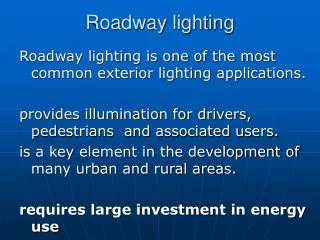
Outdoor lighting installations Lighting fixtures along with their supply circuits, including: transformers, breakers, reclosers, switches, manholes, and whatever is functional to the installation performance. All publicly exposed!
Stray Voltages “Stray”: Element or occurrence not desired in theory, but unavoidable in a practical realization. Term coined in the 1970s: Stray Voltages In Dairies “Elevated metal object-to-ground or neutral-to-ground voltages” Current, and not Voltage, is the proper criterion of shock intensity
Stray Currents Concerns for pedestrians and their animals! • Permanent current • other than momentary fault current • circulating over the earth • objectionable and undesirable
TT earthing systemper IEC T T T= direct connection of one point of the power system to ground. T= directelectrical connection of exposed-conductive-parts to ground, independently of the grounding of any point of the power system Utility Customer
TT earthing system The intensity of the ground fault current is limited by the series resistance RL and RN of the grounds. RCD is crucial!
Drawbacks with the RCDs Nuisance trips e.g. transient (10 μs) overvoltages during thunderstorms RCD trips the breaker in 10-40 ms: it operates when the impulse has already expired. RCD with intentional tripping delay is allowed, better if with high immunity to disturbances.
RCD with automatic reclosure capability? Not required, so far, by IEC standards because of the risk of repetitive shock to persons due to a persistent fault. Professional Engineers must decide on an individual case basis!
TT Equivalent fault circuit Person’s body resistance: 788Ω @125V, 700 Ω @220 V, etc. VOLTAGE DIVIDER! Person’s resistance to ground in the absence of floor: 2ρ. Person assumed shoeless as per: IEC 60479-1; 1994-09, 3rd Ed., “Effects of current on human beings and livestock - Part 1: General aspects”. Persons in contact with the energized pole, and standing in its proximity, are in an area at a potential other than zero. This circumstance limits the source touch voltage VST!
What if the neutral conductor is faulted? Independently grounded poles in TT Systems the RCD is desensitized!
Independently grounded poles in TT Systems No, thank you!
TN-C-S Earthing System T N -C -S T= direct connection of one point to ground. S= protective function provided by a conductor separate from the grounded conductor N= direct electrical connection of the ECPs to the grounded point of the power system. C= neutral and protective functions combined in a single conductor
No-Fault Condition Stray current as a result of unbalanced loads: Permanent!
Fault Condition The fault current’s return path to the power-supply winding
Vph(V) Disconnecting time ta (s) 120 0.8 230 0.4 277 0.4 400 0.2 >400 0.1 TN-C-S Earthingsystems Iais the current causing the automatic operation of the overcurrent protective device within the safe timeta DOSE!
Extraneous-conductive-part (EXCP) Conductive part: • not forming part of the electrical system • liable to introduce a “zero” potential (local/remote earth potential) or • an arbitrary potential
Whole potential between the faulted pole and the fence Should we bond? EXCP EXCP Bonding Jumper between pole and fence (only if Extraneous-Conductive-Part) Drawback: Ground Potential Rises are tranferred!
Class II equipment Double insulated (or reinforced insulated) equipment: incorporates a supplementary insulation, in addition to the basic one. The two insulations are physically separated (and tested) they cannot be subject to the same deteriorating factors (e.g. temperature, contaminants, etc.) to the same degree.
Class II equipment According to IEC, class II equipment isnot permittedto be grounded. It is an equivalent protection against indirect contacts if applied to the entire outdoor installation (i.e. light fixtures, conductors, splices, and terminal strip). According to NEC, double insulated equipment isnot requiredto be grounded.
Persons are sensitive to currents, and not to voltages. Stray voltages, thus, cannot point out, per se, dangerous situations. Measuring stray voltages The human body resistance RB is variable with the touch voltage. Touch-voltage must be measured with reference to a standard human body resistance value: 1 kΩ as per IEC It is important to assess the capability of the stray voltage to impress a dangerous current and not the magnitude of the voltage itself.
Is the faulted pole found? Poles’ enclosures are connected together. The presence of stray voltage at the pole under investigation does not necessarily mean a fault on it!
Conclusions Analysis of the fault-loops is crucial to understand the causes of stray voltages. TT and TN-C-S distribution systems have fault loops of different natures, the first one comprising the actual earth. Both distribution systems require an effective partnership between the protective device and the grounding system, in order to protect persons by automatic disconnection of supply. Class II installations are an efficient solution to protect persons from electrocution and preserve the continuity of the service, especially in areas at high pedestrian and/or vehicular circulation.
“Stray Voltages and Publicly Exposed Lighting Installations” • References • M. Mitolo, “On Outdoor Lighting Installations Grounding Systems”, IEEE-IAS “Industry Application Society 41st Annual Meeting”, Tampa, Fl, October 2006. • IEC 60364-1; 2002-06, 2nd Edition, “Electrical installations of buildings”. • M. Mitolo, “Protective bonding conductors: an IEC point of view”, I&CPS Technical Conference 2005, Saratoga Springs, NY, Proceedings. • IEC 60479-1; 1994-09, 3rd Edition, “Effects of current on human beings and livestock - Part 1: General aspects”. • IEC 60364-7-717; 1996-04, 1st Edition, “Electrical installations of buildings”, part 7. “Requirements for special installations or locations - Section 714: External lighting installations”. • NFPA 70, National Electrical Code2005, National Fire Protection Association, Quincy, Massachusetts. • IEEE Std. 142-1991, “IEEE Recommended Practice for Grounding of Industrial and Commercial Power Systems”. • British Standard BS 7671; 2001, 16th Edition“IEE Wiring Regulations”. • “Stray Voltages, Concerns, Analysis and Mitigation”, NEETRAC Project, Number 00-092, September 2001.