Download
1 / 12
130 likes | 416 Views
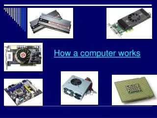
Elements of the Computer (How a processor works). C.S. French Chapter 19. The Computer itself. Processor. Memory. Control Unit. ALU. 1 2 3 4 5 6 7 8 9 10 11 12. CIR. Accumulator. SCR. Input Output Unit. Peripheral Devices. MAR. MDR. Data Bus. Terms. Memory

E N D
Elements of the Computer(How a processor works) C.S. French Chapter 19
The Computer itself. Processor Memory Control Unit ALU 1 2 3 4 5 6 7 8 9 10 11 12 CIR Accumulator SCR Input Output Unit Peripheral Devices MAR MDR Data Bus
Terms • Memory • main memory (RAM), electronic, fast, volatile, expensive, holds data currently in use. • made up of many general purpose storage locations. • may hold data or instructions. • locations referred to by their ‘addresses’. • Data Bus • a set of wires for transmitting data. • Processor • controls the computer and carries out processing. • Register • a special purpose storage location in the processor. • Control Unit • controls the loading and execution of instructions. • MDR (Memory Data Register) • holds data temporarily as it enters and leaves the processor.
More Terms • ALU (Arithmetic and Logic Unit) • carries out arithmetic and logic operations. (add, subtract, AND, NOT etc) • Accumulator • holds the result of the last operation carried out by the ALU. • CIR (Current Instruction Register) • holds the instruction that is currently being interpreted and executed by the Control Unit. • MAR (Memory Address Register) • holds the address of the memory location which is currently connected to the data bus. (controls access to memory) • SCR (Sequence Control Register) • holds the address of the memory location of the instruction that is to be executed after the current one is finished. • this is ‘incremented’ by 1 each time it is copied to the MAR.
Peripheral Devices • Input • keyboard, mouse, bar-code readers, camera, microphone etc • Output • screen, printer, plotter, mechanical device etc. • Communications • modem, ISDN adaptor, network card etc. • Backing Storage • slow, non-volatile, usually mechanical, cheap. • floppy disk, hard disk, CDROM, magnetic tape, zip disk
How the computer works. • Machine instructions and data are stored in memory in binary format. • A machine instruction consists of 2 parts: • Operation code: holds the binary code for the operation that is to be carried out by the processor. • Operand address: this is the address in memory where the processor may find the data that is to be operated on. • Machine instructions are ‘fetched’ from memory and then ‘executed’ by the processor. From this slide and the next, 1st years would be expected to be able to describe the principle of the fetch/execute cycle as opposed to the details of how this cycle is implemented.
The Fetch/Execute cycle. • The address of the next instruction to be executed is copied from the SCR to the MAR. • The SCR is incremented by 1. • The information is copied from memory to the MDR. • The contents of the MDR is copied to the CIR. • The operation code part of the instruction in the MDR is copied to the control unit. • The control unit recognises the instruction and executes it (the execution will vary depending on the instruction).
The LOAD instruction.(Not required for 1st years) • Purpose: to load data from memory to the accumulator. • The operation address part of the CIR is copied to the MAR. • The location in memory is copied to the MDR. • The MDR is copied to the accumulator.
The STORE instruction(Not required for 1st years) • Purpose: to copy the contents of the accumulator to a location in memory. • The operation address part of the CIR is copied to the MAR. • The accumulator is copied to the MDR. • The MDR is copied to the location in memory .
The ADD instruction(Not required for 1st years) • Purpose: to add the contents of a memory location to the contents of the accumulator. • The operand address in the CIR is copied to the MAR. • The contents of memory is copied to the MDR. • The MDR contents are copied to the ALU which adds it to the accumulator, placing the result in the accumulator.
The JUMP instruction. (Not required for 1st years) • Purpose: to transfer control in a program to an instruction other than the next one. • The contents of the operand address are copied to the SCR. • Variations: • JUMP NEGATIVE • JUMP ZERO • JUMP POSITIVE • The contents of the operand address are only copied to the SCR if the accumulator is in the correct condition.
Machine language exercises(Not required for 1st years) • Given the binary codes for these machine instructions write the programs described below. • LOAD 0001 • STORE 0010 • ADD 0011 • JUMP 0100 • JUMP + 0101 • JUMP - 0110 • JUMP 0 0111 • Program to add together the contents of memory locations 10 and 11 and store the result in location 12. • Program to count down from 9 to zero.