An Overview of Electronic Component Reliability
290 likes | 744 Views
An Overview of Electronic Component Reliability. Michael Choi Cornell B.S. E.E. ‘99 Cornell M.Eng E.E. ‘00. Abstract.

An Overview of Electronic Component Reliability
E N D
Presentation Transcript
An Overview of Electronic Component Reliability Michael Choi Cornell B.S. E.E. ‘99 Cornell M.Eng E.E. ‘00
Abstract • In order to release an electronic component into the market, a series of evaluations exerting electrical and environmental stress must be performed in order to prove out component reliability. To carry out these evaluations without gating product release, elevated stress conditions are used in shorter durations and compared against lifetime usage of the component.
Outline • Quality vs Reliability • Bathtub Curve • Common Failure Mechanisms • Burn-in • Survey of Common Reliability Evaluations • Usage Models • Summary
Quality vs Reliability • Quality is a measure of overall product health at the time of release (i.e. percentage of products that are functional at shipment) • Reliability is a measure of overall product health over the expected lifetime of the product.
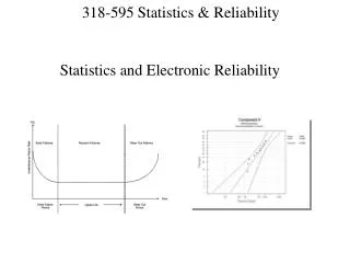
The Bathtub Curve • Infant Mortality • Decreasing failure rate due to early life fails that were not caught at production test. • Normal Life • Constant failure rate since early life fails have been weeded out. These are random failures. • Wearout • This is the end of life for electronic components. The failure rate increases because operation is beyond what the component was designed to do.
Common Failure Mechanisms • Silicon • Gate oxide pinhole • Metal-to-metal short • Package • Cu-line migration • Delamination • Silicon-Package interaction • Die cracking
Burn-in • What is burn-in? • Burn-in is a method to stress silicon to emulate the type of stress it would undergo in its normal life in a shorter span. • Why do burn-in? • For any product, an assessment of the reliability over the intended lifetime of product is necessary to protect the customer. • How is burn-in done? • Utilizing the built-in logic test functionality, the silicon operates at a higher voltage and temperature than normal to induce a faster degradation
Temperature Acceleration • One common way to understand how time-to-fail varies with temperature is the empirically based Arrhenius equation. It takes the form: • The acceleration factor between operation at two different temperatures is:
Voltage Acceleration • Voltage acceleration can also follow an exponential dependency: • Typically, voltage acceleration is much more effective at stressing silicon devices than temperature acceleration.
Temperature/Voltage Stress Use • Temperature and voltage stress accelerate different failure mechanisms in varying ways depending on the process technology. Each technology will be affected differently depending on: • Susceptibility to different types of failure mechanisms • Design rules for the process technology
Burn-in Equipment • Burn-in is one of the main tools for assessing product reliability. It requires equipment to run the evaluation: • Burn-in socket: holds the product and connects it to the burn-in board. • Burn-in board: board which holds an array of sockets and routes signals to each socket. • Burn-in oven: provides the vector patterns to stress logic in the device and regulates temperature.
Reliability Evaluation • With the increasing complexity of devices, there are an increasing number of failure mechanisms and evaluations to assess them. Here are some of the common ones: • Silicon: • Life stress test (burn-in) • Electrostatic Discharge (ESD) • Package • Temperature Cycling • Highly Accelerated Stress Test (HAST)
ESD • Electrostatic discharge occurs when charge flows from one place to another and an equilibrium is reached. • Two objects with different potentials come into contact and current flows between them. • This potential difference can be in the 1000s of volts and cause amps of current to flow in nanoseconds. • Unprotected CMOS devices will be blown-out with less than 100V of potential difference. • Thus, electronic components require ESD circuit protection to handle these potentials on the input/output pins.
ESD continued • Sources of ESD can come from anywhere: • Human touch • Manufacturing process • Carpet • Thus, different ESD tests are done to cover different sources: • Human body model (HBM) • Machine model (MM) • Charged device model (CDM)
Temperature Cycling • Temperature cycling swings a packaged component from sub-zero to high temperatures to stress the package. • The temperature cycling evaluation typically takes a sample of functionally good components and cycles them. These parts are then tested afterwards to check for functionality. • Typical failures: • Package delamination • Die cracking
HAST • HAST exposes a packaged component to thermal and humidity stress. • The components sit in a chamber which creates conditions of high temperature and a high relative humidity. • Sometimes a biased HAST is done to exert voltage stress on the package metal traces. • Typical failure modes: • Delamination • Die-cracking • Metal line migration (biased)
Usage Models • Many evaluations exist for different applications and different types. • Each of the aforementioned evaluations (ESD, HAST, Temperature Cycling) has different versions to fit different usage models. • Therefore, for a given electronic component, a usage model must be developed to figure out what stresses should be used to emulate a true life test.
Usage Models continued • Usage models vary greatly from component to component. Here are some cases: • Desktop computer • Not mobile, operates inside. • Notebook computer • Mobile, operates in a variety of temperature, humid conditions. Might get dropped. • Cellphone • Mobile, operates in a variety of temperature, humid conditions. Will get dropped. • In addition, each of these devices has a different expected usage life. • Thus, understanding the usage of the electronic component is essential to ensuring proper reliability for the consumer.
Summary • Quality and reliability are major concerns for any electronic component used today. • Through reliability stress, we can understand what makes our products weak and address those issues before they affect customers. • In order to properly stress electronic components, we must first understand how they are used.