Download
1 / 109
1.14k likes | 1.34k Views
Basic Electronics (Outline). The Elements of Electricity Volt-Ohm-Meter Basics (Measuring Electricity) Circuit Diagrams Basics (Electronic Roadmaps) The Resistor Ohm’s Law The Capacitor The Inductor The Diode The Transistor (Electronic Valve). The Elements of Electricity. Voltage

E N D
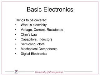
Basic Electronics (Outline) • The Elements of Electricity • Volt-Ohm-Meter Basics (Measuring Electricity) • Circuit Diagrams Basics (Electronic Roadmaps) • The Resistor • Ohm’s Law • The Capacitor • The Inductor • The Diode • The Transistor (Electronic Valve)
The Elements of Electricity • Voltage • Current • Resistance • Types of Current: AC and DC • Circuits • Closed • Open • Short
Voltage, Current, and Resistance • Water flowing through a hose is a good way to imagine electricity Water is like Electrons in a wire (flowing electrons are called Current) Pressureis the force pushing water through a hose – Voltage is the force pushing electrons through a wire Friction against the holes walls slows the flow of water – Resistance is an impediment that slows the flow of electrons
Forms of Current • There are 2 types of current • The form is determined by the directions the current flows through a conductor • Direct Current (DC) • Flows in only one direction from negative toward positive pole of source • Alternating Current (AC) • Flows back and forth because the poles of the source alternate between positive and negative
AC Current Vocabulary Time Period of One Cycle
Circuits • A circuit is a path for current to flow • Three basic kinds of circuits • Open – the path is broken and interrupts current flow • Closed – the path is complete and current flows were it is intended • Short – an unintended low resistance path that divers current
Common Functions Voltage AC/DC Ranges Current AC/DC Ranges Resistance (DC only) Ranges Continuity Semi-conductor Performance Transistors Diodes Capacitance Volt-Ohm-Meter (VOM) Basics(Measuring Electricity)
Volt-Ohm-Meter Basics Meter Reading Digits DC Voltage Scales AC Voltage Scales Function Selection Jacks
Volt-Ohm-Meter Basics DC Current (low) DC Current (high) Resistance Transistor Checker Diode Checker
Measuring Current Positive Source Negative Source
Measuring Resistance • When the VOM is used to measure resistance, what actually is measured is a small current applied to the component. • There are 5 ranges. An out of resistance reading will be indicated by a single “1” digit. Remember k means multiply the reading by 1000. • Operating voltages should be removed from the component under test or you could damage the VOM at worst, or the reading could be in error at best.
Circuit Diagrams Basics (Electronic Roadmaps) • Component Representations • Resistor • Ground • Capacitor • Inductor • Diode • Transistor • Integrated circuit • Special
Resistor Variable Fixed
Ground Earth Chassis
Capacitor Fixed Variable
Inductor Variable Air Core Iron Core
Diode Light Emitting (LED) General Purpose Zener
Transistor NPN PNP FET
Special Speaker Battery Voltmeter Antenna Fuse Ampmeter
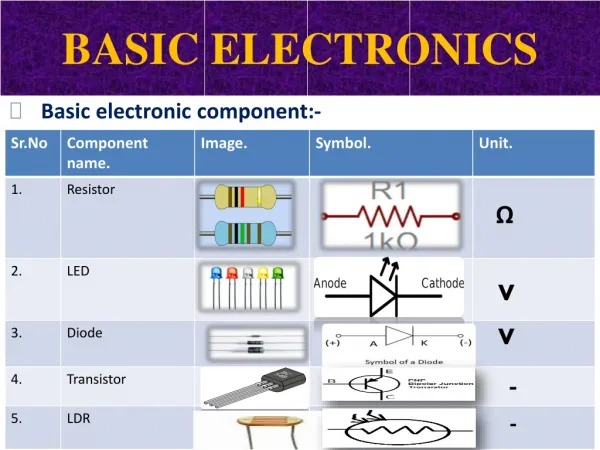
The Resistor • Resistance defined • Resistance values • Ohms – color code interpretation • Power dissipation • Resistors in circuits • Series • Parallel • Combination
Resistance Defined • Resistance is the impediment to the flow of electrons through a conductor • (friction to moving electrons) • Where there’s friction, there is heat generated • All materials exhibit some resistance, even the best of conductors • Unit measured in Ohm(s) • From 1/10 of Ohms to millions of Ohms
Resistor Types • Fixed Value • Variable value • Composite resistive material • Wire-wound • Two parameters associated with resistors • Resistance value in Ohms • Power handling capabilities in watts
All 1000 Ohm Resistors 1/8 ¼ ½ 1 2 20
Reading Resistor Color Codes • Turn resistor so gold, silver band, or space is at right • Note the color of the two left hand color bands • The left most band is the left hand value digit • The next band to the right is the second value digit • Note the color of the third band from the left, this is the multiplier • Multiply the 2 value digits by the multiplier
Reading Resistor Color Codes(Practice Problems) • Orange, orange, red? • Yellow, violet, orange? • Brown, black, brown? • Brown, black, green? • Red, red, red? • Blue, gray, orange? • Orange, white, orange?
Power dissipation • Resistance generates heat and the component must be able to dissipate this heat to prevent damage. • Physical size (the surface area available to dissipate heat) is a good indicator of how much heat (power) a resistor can handle • Measured in watts • Common values ¼, ½, 1, 5, 10 etc.
Looking at the current path, if there is only one path, the components are in series. Resistors in CircuitsSeries
If there is more than one way for the current to complete its path, the circuit is a parallel circuit. Resistors in CircuitsParallel
Resistors in CircuitsParallel Challenge • Make a circuit with 3 resistors in parallel, calculate the equivalent resistance then measure it. • R1 = 330 ohm • R2 = 10 k-ohm • R3 = 4.7 k-ohm
If the path for the current in a portion of the circuit is a single path, and in another portion of the circuit has multiple routes, the circuit is a mix of series and parallel. Resistors in CircuitsMixed
Take the parallel segment of the circuit and calculate the equivalent resistance: Resistors in CircuitsMixed R1 330 R3 2.2K R2 4.7K
We now can look at the simplified circuit as shown here. The parallel resistors have been replaced by a single resistor with a value of 1498 ohms. Calculate the resistance of this series circuit: Resistors in CircuitsMixed R1 330 RE=1498
In this problem, divide the problem into sections, solve each section and then combine them all back into the whole. R1 = 330 R2 = 1K R3 = 2.2K R4 = 4.7K Resistors in CircuitsMixed R1 R2 R4 R3
Looking at this portion of the circuit, the resistors are in series. R2 = 1k-ohm R3 = 2.2 k-ohm Resistors in CircuitsMixed R2 R3
Substituting the equivalent resistance just calculated, the circuit is simplified to this. R1 = 330 ohm R4 = 4.7 k-ohm RE = 3.2 k-ohm Now look at the parallel resistors RE and R4. Resistors in CircuitsMixed R1 RE R4
Using the parallel formula for: RE = 3.2 k-ohm R4 = 4.7 k-ohm Resistors in CircuitsMixed R4 RE
The final calculations involve R1 and the new RTotal from the previous parallel calculation. R1 = 330 RE = 1.9K Resistors in CircuitsMixed R1 RTotal
Resistors in CircuitsMixed R1 = 330 ohm RTotal = 2,230 = R2 = 1 k-ohm R4 = 4.7 k-ohm R3 = 2.2 k-ohm
Ohm’s Law • The mathematical relationship • E=I*R • Doing the math • Kirchhoff’s law • A way to predict circuit behavior • It all adds up • Nothing is lost