Download
1 / 35
360 likes | 637 Views
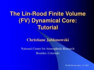
The Lin-Rood Finite Volume (FV) Dynamical Core: Tutorial. Christiane Jablonowski National Center for Atmospheric Research Boulder, Colorado. NCAR Tutorial, May / 31/ 2005. Topics that we discuss today. The Lin-Rood Finite Volume (FV) dynamical core History: where, when, who, …

E N D
The Lin-Rood Finite Volume (FV) Dynamical Core:Tutorial Christiane Jablonowski National Center for Atmospheric ResearchBoulder, Colorado NCAR Tutorial, May / 31/ 2005
Topics that we discuss today • The Lin-Rood Finite Volume (FV) dynamical core • History: where, when, who, … • Equations & some insights into the numerics • Algorithm and code design • The grid • Horizontal resolution • Grid staggering: the C-D grid concept • Vertical grid and remapping technique • Practical advice when running the FV dycore • Namelist and netcdf variables variables (input & output) • Dynamics - physics coupling • Hybrid parallelization concept • Distributed-shared memory parallelization approach: MPI and OpenMP • Everything you would like to know
Who, when, where, … • FV transport algorithm developed by S.-J. Lin and Ricky Rood (NASA GSFC) in 1996 • 2D Shallow water model in 1997 • 3D FV dynamical core around 1998/1999 • Until 2000: FV dycore mainly used in data assimilation system at NASA GSFC • Also: transport scheme in ‘Impact’, offline tracer transport • In 2000: FV dycore was added to NCAR’s CCM3.10 (now CAM3) • Today (2005): The FV dycore • might become the default in CAM3 • Is used in WACCAM • Is used in the climate model at GFDL
Dynamical cores of General Circulation Models Dynamics Physics FV: No explicit diffusion (besides divergence damping)
The NASA/NCAR finite volume dynamical core • 3D hydrostatic dynamical core for climate and weather prediction: • 2D horizontal equations are very similar to the shallow water equations • 3rd dimension in the vertical direction is a floating Lagrangian coordinate: pure 2D transport with vertical remapping steps • Numerics: Finite volume approach • conservative and monotonic 2D transport scheme • upwind-biased orthogonal 1D fluxes, operator splitting in 2D • van Leer second order scheme for time-averaged numerical fluxes • PPM third order scheme (piecewise parabolic method)for prognostic variables • Staggered grid (Arakawa D-grid for prognostic variables)
The 3D Lin-Rood Finite-Volume Dynamical Core Momentum equation in vector-invariant form Continuity equation Pressure gradient term in finite volume form Thermodynamic equation, also for tracers (replace ): The prognostics variables are: p: pressure thickness, =Tp-: scaled potential temperature
Finite volume principle Continuity equation in flux form: Integrate over one time step t and the 2D finite volume with area A: Integrate and rearrange: Time-averagednumerical flux Spatially-averagedpressure thickness
Finite volume principle Apply the Gauss divergence theorem: unit normal vector Discretize:
Orthogonal fluxes across cell interfaces Flux form ensures mass conservation G i,j+1/2 F i-1/2,j F i+1/2,j (i,j) G i,j-1/2 Upwind-biased: Wind direction F: fluxes in x directionG: fluxes in y direction
Quasi semi-Lagrange approach in x direction CFLy = v * t/y < 1 required G i,j+1/2 F i-5/2,j F i+1/2,j (i,j) G i,j-1/2 CFLx = u * t/y > 1 possible: implemented as an integer shift and fractional flux calculation
Numerical fluxes & subgrid distributions • 1st order upwind • constant subgrid distribution • 2nd order van Leer • linear subgrid distribution • 3rd order PPM (piecewise parabolic method) • parabolic subgrid distribution • ‘Monotonocity’ versus ‘positive definite’ constraints • Numerical diffusion Explicit time stepping scheme: Requires short time steps that are stable for the fastest waves (e.g. gravity waves) CGD web page for CAM3: http://www.ccsm.ucar.edu/models/atm-cam/docs/description/
Subgrid distributions:constant (1st order) x1 x2 x3 x4 u
Subgrid distributions:piecewise linear (2nd order) van Leer x1 x2 x3 x4 u See details in van Leer 1977
Subgrid distributions:piecewise parabolic (3rd order) PPM x1 x2 x3 x4 u See details in Carpenter et al. 1990 and Colella and Woodward 1984
Monotonicity constraint • Prevents over- and undershoots • Adds diffusion not allowed van Leer Monotonicity constraint resultsin discontinuities x1 x2 x3 x4 u See details of the monotinity constraint in van Leer 1977
Simplified flow chart subcycled 1/2 t only: compute C-grid time-mean winds stepon dynpkg cd_core c_sw d_p_coupling trac2d physpkg te_map full t: update all D-grid variables d_sw p_d_coupling Vertical remapping
Grid staggerings (after Arakawa) B grid u v u v A grid u v u v u v C grid v u D grid u v v u Scalars: v u
Regular latitude - longitude grid • Converging grid lines at the poles decrease the physical spacing x • Digital and Fourier filters remove unstable waves at high latitudes • Pole points are mass-points
Typical horizontal resolutions • Time step is the ‘physics’ time step: • Dynamics are subcyled using the time step t/nsplit • ‘nsplit’ is typically 8 or 10 • CAM3: check (dtime=1800s due to physics ?) • WACCAM: check (nsplit = 4, dtime=1800s for 2ox2.5o ?) Defaults:
Idealized baroclinic wave test case The coarse resolution does not capture the evolution of the baroclinic wave Jablonowski and Williamson 2005
Idealized baroclinic wave test case Finer resolution: Clear intensification of the baroclinic wave
Idealized baroclinic wave test case Finer resolution: Clear intensification of the baroclinic wave, it starts to converge
Idealized baroclinic wave test case Baroclinic wave pattern converges
Idealized baroclinic wave test case:Convergence of the FV dynamics Global L2 error norms of ps Solution starts converging at 1deg Shaded region indicates the uncertainty of the reference solution
Floating Lagrangian vertical coordinate • 2D transport calculations with moving finite volumes (Lin 2004) • Layers are material surfaces, no vertical advection • Periodic re-mapping of the Lagrangian layers onto reference grid • WACCAM: 66 vertical levels with model top around 130km • CAM3: 26 levels with model top around 3hPa (40 km) • http://www.ccsm.ucar.edu/models/atm-cam/docs/description/
Physics - Dynamics coupling • Prognostic data are vertically remapped (in cd_core) before dp_coupling is called (in dynpkg) • Vertical remapping routine computes the vertical velocity and the surface pressure ps • d_p_coupling and p_d_coupling (module dp_coupling) are the interfaces to the CAM3/WACCAM physics package • Copy / interpolate the data from the ‘dynamics’ data structure to the ‘physics’ data structure (chunks), A-grid • Time - split physics coupling: • instantaneous updates of the A-grid variables • the order of the physics parameterizations matters • physics tendencies for u & v updates on the D grid are collected
Practical tips Namelist variables: • What do IORD, JORD, KORD mean? • IORD and JORD at the model top are different (see cd_core.F90) • Relationship between • dtime • nsplit (what happens if you don’t select nsplit or nsplit =0, default is computed in the routine d_split in dynamics_var.F90) • time interval for the physics & vertical remapping step Input / Output: • Initial conditions: staggered wind components US and VS required (D-grid) • Wind at the poles not predicted but derived User’s Guide: http://www.ccsm.ucar.edu/models/atm-cam/docs/usersguide/
Practical tips Namelist variables: • IORD, JORD, KORD determine the numerical scheme • IORD: scheme for flux calculations in x direction • JORD: scheme for flux calculations in y direction • KORD: scheme for the vertical remapping step • Available options: • - 2: linear subgrid, van-Leer, unconstrained • 1: constant subgrid, 1st order • 2: linear subgrid, van Leer, monotonicity constraint (van Leer 1977) • 3: parabolic subgrid, PPM, monotonic (Colella and Woodward 1984) • 4: parabolic subgrid, PPM, monotonic (Lin and Rood 1996, see FFSL3) • 5: parabolic subgrid, PPM, positive definite constraint • 6: parabolic subgrid, PPM, quasi-monotone constraint • Defaults: 4 (PPM) on the D grid (d_sw), -2 on the C grid (c_sw)
‘Hybrid’ Computer Architecture • SMP: symmetric multi-processor • Hybrid parallelization technique possible: • Shared memory (OpenMP) within a node • Distributed memory approach (MPI) across nodes Example: NCAR’s Bluesky (IBM) with 8-way and 32-way nodes
Schematic parallelization technique 1D Distributed memory parallelization (MPI) across the latitudes: Proc. NP 1 2 Eq. 3 4 SP 0 Longitudes 340
Schematic parallelization technique Each MPI domain contains ‘ghost cells’ (halo regions):copies of the neighboring data that belong to different processors NP Proc. 2 Eq. 3 ghostcells for PPM SP 0 Longitudes 340
Schematic parallelization technique Shared memory parallelization (in CAM3 most often) in the vertical direction via OpenMP compiler directives: Typical loop: do k = 1, plev … enddo Can often be parallelized with OpenMP (check dependencies): !$OMP PARALLEL DO … do k = 1, plev … enddo
Schematic parallelization technique Shared memory parallelization (in CAM3 most often) in the vertical direction via OpenMP compiler directives: k CPU e.g.: assume 4 parallel ‘threads’ and a 4-way SMP node (4 CPUs) !$OMP PARALLEL DO … do k = 1, plev … enddo 1 1 4 5 2 8 3 4 plev
Thank you !Any questions ??? • Tracer transport ? • Fortran code • …
References • Carpenter, R., L., K. K. Droegemeier, P. W. Woodward and C. E. Hanem 1990: Application of the Piecewise Parabolic Method (PPM) to Meteorological Modeling. Mon. Wea. Rev., 118, 586-612 • Colella, P., and P. R. Woodward, 1984: The piecewise parabolic method (PPM) for gas-dynamical simulations. J. Comput. Phys., 54,174-201 • Jablonowski, C. and D. L. Williamson, 2005: A baroclinic instability test case for atmospheric model dynamical cores. Submitted to Mon. Wea. Rev. • Lin, S.-J., and R. B. Rood, 1996: Multidimensional Flux-Form Semi-Lagrangian Transport Schemes. Mon. Wea. Rev., 124, 2046-2070 • Lin, S.-J., and R. B. Rood, 1997: An explicit flux-form semi-Lagrangian shallow water model on the sphere. Quart. J. Roy. Meteor. Soc., 123, 2477-2498 • Lin, S.-J., 1997: A finite volume integration method for computing pressure gradient forces in general vertical coordinates. Quart. J. Roy. Meteor. Soc., 123, 1749-1762 • Lin, S.-J., 2004: A ‘Vertically Lagrangian’ Finite-Volume Dynamical Core for Global Models. Mon. Wea. Rev., 132, 2293-2307 • van Leer, B., 1977: Towards the ultimate conservative difference scheme. IV. A new approach to numerical convection. J. Comput. Phys., 23. 276-299