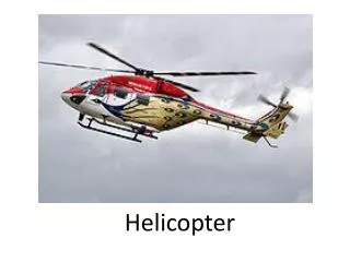
Helicopter Limited Icing Approval
121 likes | 662 Views
Helicopter Limited Icing Approval. JAR 29 Special Condition Ray White (UK CAA) 25/5/2005. 30 Years UK Sector North Sea Experience. Requirement Basis. All current aircraft were validated by UK CAA against BCAR Section G, or BCAR-29 (AS332L2)

Helicopter Limited Icing Approval
E N D
Presentation Transcript
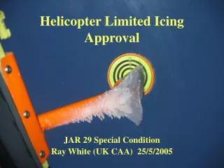
Helicopter Limited Icing Approval JAR 29 Special Condition Ray White (UK CAA) 25/5/2005
Requirement Basis • All current aircraft were validated by UK CAA against BCAR Section G, or BCAR-29 (AS332L2) • Limited Icing approved in accordance with BCAR Paper G610 • For EC225, EASA invited UK CAA to develop a Special Condition to JAR 29, based on the principles of G610
Requirements for Icing Approval • JAR 29.1419 • CS 29.1419 lce protection • (a) To obtain certification for flight into icing conditions, compliance with this paragraph must be shown. • (b) It must be demonstrated that the rotorcraft can be safely operated in the continuous maximum and intermittent maximum icing conditions determined under Appendix C within the rotorcraft altitude envelope. An analysis must be performed to establish, on the basis of the rotorcraft’s operational needs, the adequacy of the ice protection system for the various components of the rotorcraft. • (c) In addition to the analysis and physical evaluation prescribed in sub-paragraph (b) of this paragraph, the effectiveness of the ice protection system and its components must be shown by flight tests of the rotorcraft or its components in measured natural atmospheric icing conditions and by one or more of the following tests as found necessary to determine the adequacy of the ice protection system: • (1) Laboratory dry air or simulated icing tests, or a combination of both, of the components or models of the components. • (2) Flight dry air tests of the ice protection system as a whole, or its individual components. • (3) Flight tests of the rotorcraft or its components in measured simulated icing conditions. • (d) The ice protection provisions of this paragraph are considered to be applicable primarily to the airframe. Powerplant installation requirements are contained in Subpart E of this CS–29. • (e) A means must be identified or provided for determining the formation of ice on critical parts of the rotorcraft. Unless otherwise restricted, the means must be available for night-time as well as daytime operation. The rotorcraft flight manual must describe the means of determining ice formation and must contain information necessary for safe operation of the rotorcraft in icing conditions.
JAR 29, Appendix C • (a) Continuous maximum icing. The maximum continuous intensity of atmospheric icing conditions (continuous maximum icing) is defined by the variables of the cloud liquid water content, the mean effective diameter of the cloud droplets, the ambient air temperature, and the interrelationship of these three variables as shown in Figure 1 of this Appendix. The limiting icing envelope in terms of altitude and temperature is given in Figure 2 of this Appendix. The interrelationship of cloud liquid water content with drop diameter and altitude is determined from Figures 1 and 2. The cloud liquid water content for continuous maximum icing conditions of a horizontal extent, other than 32.2 km (17.4 nautical miles), is determined by the value of liquid water content of Figure 1, multiplied by the appropriate factor from Figure 3 of this Appendix. • (b) Intermittent maximum icing. The intermittent maximum intensity of atmospheric icing conditions (intermittent maximum icing) is defined by the variables of the cloud liquid water content, the mean effective diameter of the cloud droplets, the ambient air temperature, and the interrelationship of these three variables as shown in Figure 4 of this Appendix. The limiting icing envelope in terms of altitude and temperature is given in Figure 5 of this Appendix. The interrelationship of cloud liquid water content with drop diameter and altitude is determined from Figures 4 and 5. The cloud liquid water content for intermittent maximum icing conditions of a horizontal extent, other than 4.8 km (2.6 nautical miles), is determined by the value of cloud liquid water content of Figure 4 multiplied by the appropriate factor in Figure 6 of this Appendix.
AC29.1419 • a. (4) The icing characteristics envelope of FAR Part 25, Appendix C, has served as a satisfactory design criteria for fixed‑wing operations for two decades. The envelope, as presented, extends to 22,000 feet with possible extension to 30,000 feet but does not present icing severity as a function of altitude. At the time the envelope was derived, it was assumed that all transport category airplanes would operate to at least 22,000 feet. For present state‑of‑the‑art rotorcraft, this assumption is not valid. As such, an altitude‑limited icing envelope based on the same data used to derive the Part 25, Appendix C, and the Part 29, Appendix C, envelopes is presented as an alternate to the full icing envelope.
Limited Icing Approval Basic Principles • Applicable to large Rotorcraft only • Rotor Systems not protected, but rely on natural tolerance to “limited” ice accretion • Systems essential to safety of flight e.g. engines, pitot/static, windscreens etc must be fully protected against effects of ice • Must be Cat A and IFR compliant • Intakes must have a full snow clearance
Basic principles, contd. • The aircraft must continue to comply with relevant sections of JAR 29 in iced state • Handling – including capability to enter and recover from autorotation • Stability • Performance • Vibration • Loads • Fatigue • Flutter • Ice detection, including identification of ice accretion on areas of airframe not visible to crew
Limited? • A demonstrated and practical set of atmospheric conditions and airworthiness limitations within which the rotorcraft may be safely operated in icing conditions. • Must be defined in terms of parameters readily available to, and observable by, the operating crew. • Typically limited in terms of some or all of the following: • ·Altitude • ·OAT • ·Liquid Water Content (LWC) • ·Aircraft Mass • ·Airspeed • ·Power required • ·Vibration levels • ·Manœuvre limitations e.g. maximum bank angle • ·Ice accretion limits on unprotected areas of the airframe e.g. horizontal stabiliser • ·Duration, but only in the context of short term exposure.
Fundamentals • The limitations must include a clearance for continuous operation (i.e. not time limited) • A means of vacating the icing environment to conditions in which the rotor and airframe can de-ice naturally must be established • Compliance with the SC does not constitute an operational approval. • Ops Rules are essential to ensure the aircraft is operated within the established limiting parameters