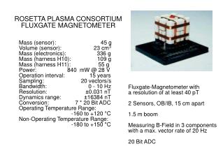
Instrument Design Fluxgate Magnetometer (FGM) Werner Magnes Institut fuer Weltraumforschung (IWF)
Instrument Design Fluxgate Magnetometer (FGM) Werner Magnes Institut fuer Weltraumforschung (IWF) Austrian Academy of Sciences Hans-Ulrich Auster Institut fuer Geophysik und Meteorologie Technical University Braunschweig (TU-BS). FGM Team. TU Braunschweig IWF Graz

Instrument Design Fluxgate Magnetometer (FGM) Werner Magnes Institut fuer Weltraumforschung (IWF)
E N D
Presentation Transcript
Instrument Design • Fluxgate Magnetometer (FGM) • Werner Magnes • Institut fuer Weltraumforschung (IWF) • Austrian Academy of Sciences • Hans-Ulrich Auster • Institut fuer Geophysik und Meteorologie • Technical University Braunschweig (TU-BS)
FGM Team TU Braunschweig IWF Graz Karl-Heinz Glassmeier (Head) Wolfgang Baumjohann (Head) Ulrich Auster (FGM TM) Werner Magnes (FGM CoTM) Ingo Richter Konrad Schwingenschuh Karl-Heinz Fornacon Aris Valavanoglou Bernd Stoll Özer Aydogar Ernst Jelting Rumi Nakamura Dragos Constantinescu Tielong Zhang Yasuhito Narita Martin Volwerk Jan Grosser Andrei Runov Sebastian Schäfer Zoltan Vörös Gero Kleindienst Yoshihiro Asano Carsten Schmidt Main Subcontractor: Magson GmbH Olaf Hillenmaier Ronald Kroth
FGM Work Distribution • UCB • Parts procurement • PCB fabrication • Boom / FGS-MLI • FGE qualification • TU-BS • FGS fabrication • FGE / sensor electronics • IWF • FGE / interface electronics • TU-BS & IWF • FGS qualification • FGM calibration • FGM integration
Block Diagram • Instrumentation
FGS - FGE 6U Board with the FGE Layout FGS
FGM Requirements (1) IN.FGM-1. The FGM shall measure DC and low frequency perturbations of the magnetic field IN.FGM-2. The absolute stability of the FGM shall be less than 1nT • Determination of 3 offsets and 9 elements of the calibration matrix (scale values, non-orthogonality, sensor orientation) through in-flight calibration once per orbit • Spinning S/C provides 8 of 12 calibration numbers • Scale values are known accurately enough from pre-flight calibration • The determination of the spin axis offset can be done to 1nT accuracy by known physics during a standard orbit and to +/-0.1nT accuracy when being in solar wind
FGM Requirements (2) IN.FGM-3a. The relative stability of the FGM shall be less than 0.2nT/12hrs IN.FGM-3b. The relative stability of the FGM shall be less than 0.1nT/hr • Offset / Time: < 0.1nT/h; < 0.2nT/12hrs; < 1nT/year; • Offset / Temperature: < 0.1nT/°C • Scale value / Temp.: < 24ppm (0.8nT/°C @ 32000nT) • Orthogonality / Temp.: can be neglected IN.FGM-5. The FGM noise level @ 1Hz shall be less than 0.03nT/sqrt(Hz) • Sensor noise: < 10pT/sqrt(Hz) @ 1 Hz
FGM Requirements (3) • IN.FGM-4. The FGM digital resolution shall be less than 0.1nT • IN.FGM-6. The FGM science range shall exceed 0-1000nT • FGM provides 0.01nT digital resolution independent of the external field due to digital magnetometer principle • The maximum feedback field (range) is about 32000nT • 24 bits per field component will be sent to the IDPU • 16 bits will be selected for transmission • 10pT digital resolution if B < 320nT • 160pT digital resolution if B > 2500nT • 1.2nT digital resolution if B > 20000nT
FGM Requirements (4) • IN.FGM-7. The FGM frequency range shall exceed DC-1 Hz • FGM primary data rate is 128Hz (7.5ms measurement, 0.3ms feedback setting) • Further averaging will be done in the FGE FPGA and/or by the IDPU
Mission Requirements (2) • Needed supply voltages and currents based on VEX-MAG and bread board: • +5Vd & +2.5Vd (FPGA & DAC) 10mA • +8Va (excitation & amplifiers) 50mA (30mA+20mA) • -8Va (amplifiers) 20mA • +/-5Va (ADC) 15mA • 760mW if all voltages will be provided (+80/-0mW) • No EEE part with > 100mW power dissipation!
Mission Requirements (3) • operating temperature range (sensor/electronics): –100°C / -20°C to +65°C / +45°C • cold start (sensor/electronics): -100 °C / -50°C • survival temperature range (sensor/electronics): –100°C / -50 °C to +65°C • FGM sensor qualified for +/-100°C (Rosetta, VenusExpress)
Electrical • Instrumentation • Interfaces defined and documented: • Four-wire serial digital I/F with CLK, CMD, TMH and TML • Supply voltages as presented before • THEMIS/FGM I/F Requirements I1R3 (TH-FGM-DS-0001) • THEMIS/IDPU Backplane Specification 001H • Proposed design will meet functional requirements • Sufficient maturity in design to proceed to detailed design • Digital magnetometer design based on existing space H/W (MIR-MAG, Rosetta Lander, Venus Express) • Separate BBM for testing design changes is currently under test • Risks have been identified • Sophisticated fabrication, calibration and integration process (Europe, Berkeley and Swales)
GSE Concept • MGSE for FGS • Mu-metal can • EGSE for FGE commanding and testing • Digital interface simulator (bread board EGSE) with limited features for bread board testing (supplied by IWF) • Full functional EGSE for ETU and FM (supplied by UCB) • Themis Calibration Unit (TCU) • Three layer mu-metal can including calibration coils and mechanics for sensor rotation • Three systems located in Braunschweig, Graz and Berkeley
Mechanical & Thermal • Mechanical • Same sensor design used for Rosetta Lander and Venus Express • For Venus Express it was just qualified to • Sinusoidal vibration: 5 .. 100 Hz; 25 g • Random vibration: 20 .. 2000 Hz; 18 Grms • Quasistatic acceleration: 25 g • Thermal • One internal / collectively controlled unit: FGE • Part of the common electronics box • One external / individually controlled unit: FGS • Extended operating and non-operating temperature range • Standard Kapton-VDA MLI is sufficient • Thermal model will be supplied
Development Plans (1) • Sub-units • FGS: FluxGate Sensor • FGE: FluxGate Electronics • Models • BBM: Bread Board Model (FGE-BBM) • STM: Structural and Thermal Model (FGS-STM) • ETU: Engineering and Testing Unit (FGE-ETU1/2) • FM: Flight Model (FGS-F1/F6 and FGE-F1/F5) • Locations • US-Berkeley (UCB) • US-Swales • E-Braunschweig (TU-BS) • E-Graz (IWF)
Development Plans (2) • FGE BBM / FGE ETU
Development Plans (3) • FGS FM / FGE FM
Development Plans (4) • FGS F6 / FGE ETU-1
Peer Review Results • 21 Findings: • From No.1 - Jitter spec. of CLK8MHz should meet the FGM requirements (i.e. 10%) • To No.21 – Magnetic control plan and S/C test in GSFC coil facility (under UCB control) FGM team fully understands the findings and will take it into account during the upcoming instrument development process! • 2 RFAs: RFA FGM-1: Magnetic Cleanliness Status: UCB is working on it RFA FGM-2: Anti-Aliasing Filter Status: FGM working on it • It was always planned to implement such a filter • Final filter spec is dependant on a trade-off between anti-aliasing, data decimation and impact on the quality of the de-spinning process.