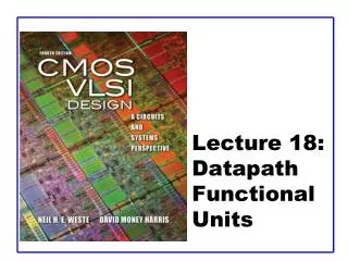
Chap. 8 Datapath Units
Chap. 8 Datapath Units. Prof. An-Yeu Wu Undergraduate VLSI Course Updated: May 24, 2002. Several Implementations of Adders. One-Bit Full Adder (Cell) Carry-Ripple Adder Transmission-Gate Adder Carry lookahead Adder Bit-Serial Adder Carry-Select Adder Conditional- Sum Adder


Chap. 8 Datapath Units
E N D
Presentation Transcript
Chap. 8 Datapath Units Prof. An-Yeu Wu Undergraduate VLSI Course Updated: May 24, 2002
Several Implementations of Adders • One-Bit Full Adder (Cell) • Carry-Ripple Adder • Transmission-Gate Adder • Carry lookahead Adder • Bit-Serial Adder • Carry-Select Adder • Conditional- Sum Adder • Manchester Adder • Very wide Adder A. Y. Wu
One-Bit Full Adder (Cell) • A and B are the adder inputs, C is the carry input, SUM is the sum output, and CARRY is the carry output. A. Y. Wu
Boolean Function A. Y. Wu
Implementation A. Y. Wu
Implementation (Cont.) A. Y. Wu
Carry-Ripple Adder • Simple & Slow • One stage delay time Tcn stages delay time nTc A. Y. Wu
Bit-Parallel Adder A. Y. Wu
Subtractor A. Y. Wu
Bit-Serial Adder A. Y. Wu
Carry-Save Adder Use register to store CARRY A. Y. Wu
CPA A. Y. Wu
Transmission-Gate Adder • Use T-G to Implement XOR Gate A. Y. Wu
Transmission-Gate Adder (Cont.) • Total 24 Transistors • SUM and CARRY have the same delay time A. Y. Wu
Reduced Tx numbers • Don’t care speed A. Y. Wu
The linear growth of adder carry-delay with the size of the input word for n-bit adder maybe improved by calculation the carries to each stage in parallel. Carry-Lookahead Adders A. Y. Wu
Carry-Lookahead Adders (Cont.) Carry of the ith stage --- Ci=Gi + PiCi-1 Gi=AiBi generate signal Pi=Ai + Bi propagate signal Expanding Ci= Gi + PiCi-1 + PiPi-1Gi-2 + ….. + Pi…P1P0 For four stages, the appropriate term : C0= G0 + P0CI C1= G1 + P1G0 + P1P0CI C2= G2 + P2G1 + P2P1G0 + P2P1P0CI C3= G3 + P3G2 + P3P2G1 + P3P2P1G0 + P3P2P1P0CI Fig1. Generic carry-lookahead adder A. Y. Wu
Carry-Lookahead Adders (Cont.) • The size and fan-in of the gates needed to implement this carry-lookahead scheme can clearly get out of hand the number of stages of lookahead is usually limited to about 4. • The circuit and layout are quite irregular. A. Y. Wu
Dynamic Carry Gates • The worst-case delay path in this circuit has six n-transistor in series. A. Y. Wu
High-speed Carry Lookahead Logic • Use pseudo-nMos to achieve high-speed static operation. A. Y. Wu
Manchester Adder Circuits A. Y. Wu
Manchester Adder Circuits (Cont.) • Dynamic stage • When CLK is low, the output node is pre-charged by the p pull-up transistor. • When CLK goes high, the pull-down transistor turns on. • If carry generate G=AB is true the output node discharges. • If carry propagate P=A+B is true a previous carry may be coupled to the output node, conditionally discharging it. • Static stage • This requires P to be generated as AB • The Manchester adder stage improves on the carry-lookahead implementation. A. Y. Wu
Manchester Adder Circuits (Cont.) • The control signals T1,T2,and T3 shown in Fig6(b) are generated by: • T1 = -(P0P1P2)P3 • T2 = -P3 • T3 = P0P1P2P3 Fig6. Manchester adder with carry bypass: (a) simple (b) conflict free A. Y. Wu
Manchester Adder Circuits (Cont.) • The worst case propagation time of a Manchester adder can be improved by bypassing the four stages if all carry-propagate signals are true. • Fig. 6(b) uses a “conflict -free” bypass circuit, which improves the speed by using a 3-input multiplexer that prevents conflicts at the wired OR node in the adder. • In Fig. 6(b), the inverter presented on the Cin signal has been moved to the center of the carry chain to improve speed. A. Y. Wu
Carry-Select Adder Fig7. Carry-select adder:(a) basic architecture (b) 32-bit carry-select adder example A. Y. Wu
Conditional-Sum Adder A. Y. Wu
Conditional-Sum Adder (Cont.) A. Y. Wu
Very Wide Adders A. Y. Wu
Very Wide Adders (Cont.) A. Y. Wu
Very Wide Adders with Bypass A. Y. Wu
Homework #5 • 利用Conditional Sum Adder做一個8-bit的加法 • Draw the schematic diagram of your design. • Verify your idea first using C or Matlab programs. • Write down the Verilog code to verify your design.Check your results with the C/Matlab results. • Due date: June 14, 2002 A. Y. Wu