Download
1 / 28
280 likes | 413 Views
STORAGE RING GIRDER INTEGRATION. Lewis Doom NSLS-II- ASAC February 1-2, 2012. OUTLINE. Girders required and Specifications 902 NSLS-II Integration Storage and work areas Major components (Girders, Magnets and vacuum chambers) Magnet assembly, pre-alignment and final alignment

E N D
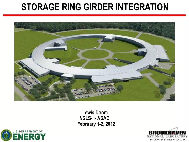
STORAGE RING GIRDER INTEGRATION Lewis Doom NSLS-II- ASAC February 1-2, 2012
OUTLINE • Girders required and Specifications • 902 NSLS-II Integration • Storage and work areas • Major components (Girders, Magnets and vacuum chambers) • Magnet assembly, pre-alignment and final alignment • Alignment requirements and results to date • Girder assembly time line, personnel requirements • Component and assembly schedule
GIRDER ASSEMBLIES All Primary Girder assemblies are modeled in detail Major assemblies include Girders (150 total required) Magnets (60 Dipoles, 300 Quadrupoles, 270 Sextupoles, 180 Correctors) 210 Vacuum chamber assemblies (150 large aluminum chambers, 30 small aluminum chambers, 30 inconelchambers) Diagnostics (370 vacuum chamber mounted buttons) Water manifolds and connections Electrical enclosures and raceways Girder 2 (30 Required) Girder 4 (30 Required) Girder 6 (30 Required) Dipole Girder (60 required)
SPECIFICATIONS • Multipole magnet alignment requirements • Vertical ±30 microns • Transverse:±30 microns • Longitudinal: ±500 microns • Roll: ±.5 mrad • Pitch: ±1.0 mrad • Yaw: ±1.0 mrad • Multipole magnet alignment is done in two stages • Preliminary alignment with laser tracker • Final alignment with vibrating wire inside temperature controlled room
BUILDING 902 NSLS-II AREAS GIRDER ASSEMBLY MAGNET RECEIVING AND STORAGE FINAL VACUUM ASSEMBLY MAGNET INSPECTION VACUUM CHAMBER ASSEMBLY GIRDER INSPECTION GIRDER STORAGE
GIRDER ASSEMBLY 902 ANEX Magnetic inspection Magnet storage Preliminary magnet alignment station 1 Girder assembly Dipole girder magnetic inspection Final magnet alignment in temperature controlled room Vacuum final assembly
GIRDER INSPECTION / SURVEY Girders are dimensionally inspected and surveyed when received using laser tracker. Inspection tooling is inserted into all magnet mounting holes and against critical surfaces A survey file for girders is generated at this time 111 out of 150 manufactured as of 1/18/2012 Four to six girders are delivered at a time and stored in the inspection area prior to being moved to primary storage Girder Survey Maximum Required: 2 girders per week Girder Survey: 4 hr / magnet Personnel required: 1 Survey Tech. (.25 FTE) Spherical mounted reflectors (SMR) Corner mounts Go/No-Go gauges for mounting slots Girder on inspection stands
MAGNET INSPECTION / SURVEY / STORAGE Magnet Inspection and Survey Maximum Required: 4 magnets per day Mechanical Inspection: 1hr / magnet Personnel required: 1 Mechanical Tech. (.5 FTE) Electrical Inspection: .5 hrs. / magnet Personnel required: 1 Electrical Tech. (.25 FTE) Magnet Survey: 1 hr. / magnet Personnel required: 1 Survey Tech. (.5 FTE) • Magnet mechanical inspection is located in building 905 • Magnet storage and receiving are in the same area • Multiple magnets are set up concurrently. All inspection is performed at one station (Survey, Hydraulic, Electrical) • Three magnetic inspection areas have been set up and are operational • Magnetic testing of all multipole magnets is being done and is expected to continue throughout production. There is adequate equipment to inspect all multipole magnets • Peak magnet delivery 74 magnets per month. 21 days per month=3.5 magnets per day Magnetic inspection Coil Resistance and Hi-Pot test Sextupoles and correctors being surveyed Survey Vibration Water flow Inspected magnets in storage
VACUUM CHAMBER Vacuum chambers are assembled and inspected prior to installation BPM spacing is noted on Traveler and provided to Survey Group Vacuum chambers are supplied to girder assembly area with a vacuum protection tube installed thru the beam pipe. BPM wiring and vacuum pumps will not be installed until after final magnet alignment. Vacuum chamber assembly Maximum Required: 2 large chamber assemblies per week BPM locations with mounts for survey balls Rigid center support Flexible carbon graphite supports with adjustable interface at chamber mounting blocks
GIRDER ASSEMBLY Girder Assembly Task Duration: 7 hrs. / girder Production rate required: 2 girders / week Personnel required: 2 (.4 FTE) • Girder assembly and pre-alignment areas are adequate for assembling up to 6 girders simultaneously as well as pre-aligning • Move girder from storage • Install threaded magnet support rods • Install water manifolds • Install vacuum chamber stands • Mount magnets on support posts centered on supports and spaced off girder • Girder can be assembled anywhere in 902 Annex
MAGNET PRE-ALIGNMENT • Position girder into pre-alignment station against banking stops • Install instrumentation (linear transducers, inclinometers • Install yaw / longitudinal positioning fixture • Pre-align each magnet using laser tracker and positioning fixtures Pre-alignment Task Duration: 3 hrs / girder Production rate: 2 girders / week Personnel required: 2 Mech. Techs, 1 survey Tech Floor plates with banking stops Girder with air casters Yaw fixture being installed Inclinometer & mount
VACUUM CHAMBER INSTALLATION Vacuum chamber installation Task Duration: 2 hrs / girder Maximum Production rate: 2 girders / week Personnel required: 2 mech. Techs, 1 survey tech. • Remove upper halves of magnets • Install and position vacuum chamber • Replace upper magnet halves • Vacuum chambers are currently positioned to better than 100 microns relative to BPMs 11
FINAL ALIGNMENT MEASUREMENT A vibrating wire measuring technique is used to find the magnetic center of each magnet A stretched wire conducting an AC current is passed through the field of each magnet. The minimum vibration of the wire indicates the center of the field. Move girder into temperature controlled room and bank against stops Allow girder temperature to soak (minimum 10 hours) Install vibrating wire Connect magnet power and diagnostics Connect water lines to magnet manifolds Run vibrating wire magnetic position routine (8 hours) Vibrating Wire Measurement Task Duration: 8 hrs / girder for full measurement Maximum Production rate: 2 girders / week Personnel required: 1 Wire Vibration detectors (~ 13 mV/micron) X-Y Stages (2.5 micron accuracy) Final magnet alignment in temperature controlled room (±.05°C) Room for second girder to soak
FINAL ALIGNMENT POSITIONING Position magnets manually with mechanical fixtures to defined locations. Confirm roll, confirm pitch and tighten to 150 foot-pounds Typical processing includes two magnet positioning sequences and three vibrating wire measurements Remove yaw control fixture and confirm magnets did not move Disconnect magnet power, magnet diagnostics, water connections, linear transducer wiring, vibrating wire Final Alignment Task Duration: 7 hrs / girder Maximum Production rate: 2 girders / week Personnel required: 2
ALIGNMENT RESULTS TO DATE Specifications require that all multipole magnets be aligned to within .030mm of the nominal centerline of a girder Get actual values from Animesh and Steve on girders manufactured to date 15
FINAL SURVEY Final Survey Task Duration: 8 hrs / girder Maximum production rate: 2 girders / week Personnel required: 1-2 • A ten tracker survey of the girder, magnets and vacuum chamber defines the as built configuration and allows for expected variation in the girder profile to be corrected in the storage ring tunnel • The girder profile is be defined for re-profiling in the storage ring • Studies have shown that a Laser tracker can reliably provide resolution of about 1 micron, Accuracy of ± 5 µm and Reproducibility of the girder/magnet system is ± 20 µm. • Remove girder from temperature controlled room Final survey being performed 16
FINAL VACUUM AND DIAGNOSTICS ASSEMBLY Move girder to final vacuum assembly and bake out area Install vacuum pumps Install vacuum bake out wiring, heaters and temperature sensors Install beam position monitor wiring and boxes Perform bake out of vacuum chamber and final leak check Area can accommodate up to 3 girders at a time Send to building 740 for installation Final Vacuum and Diagnostics assembly Task Duration: 4 days / girder Production rate: 2 girders / week Personnel required: 2
DIPOLE GIRDER INSPECTION / ASSEMBLY • 10% (6) of 35mm and 100% (6) of 90mm Dipoles will be magnetically measured • The remaining dipoles will be assembled in the NSLS-II Ring-building Experimental Floor • Vacuum chamber and magnet will be mounted on girder using a portable gantry crane and lifting beam
GIRDER INTEGRATION TASKS • Girders will be completed at a rate of two per week across two shifts (vibrating wire measurement may require three shifts.) • Girder assembly will be done on up to six girders simultaneously as parts are available • Optimizing the thermal room use and minimizing work outside two shift operations Assembly and pre-alignment is decoupled from thermal room Final alignment and survey in thermal room
GIRDER INTEGRATION TIME LINE (TWO SHIFT) • Assembly and pre-alignment is decoupled from thermal room • Girders will be completed at a rate of two per week across two shifts (vibrating wire measurement may require three shifts.) • Girder assembly will be done on up to six girders simultaneously as parts are available • Optimizing the thermal room use is the primary effort assembly Final alignment and survey 20
GIRDER PRODUCTION SCHEDULE Update with current values
MAGNET SCHEDULE Cells highlighted in green show delivered magnets as of 1/20/2011.
MULTIPOLE GIRDER PRODUCTION SCHEDULE • Production schedule by week based on available magnets and two girders per week maximum production • Girders highlighted in green are complete 23
STAFFING • Girder integration and magnet inspection • Required: • 10 mechanical technicians • 7 on first shift, 3 on second shift • 1 mechanical supervisor • 3 Survey technicians • 4 Electrical technicians 24
CONCLUSIONS Production areas have been defined and are adequate for the projected need Fixtures and measuring equipment have been tested and proven able to meet the specification requirements. Detailed time studies have been completed and are being proven to allow balancing of labor requirements across the various assembly and inspection tasks Labor requirements have been defined and are in place Integration should be complete by the end of 2012
ACKNOWLEDGMENTS Girder Integration M. Breitfeller, F. DePaola, T. Dilgen, A. Jain, F. Lincoln, M. Lucas, S. Ozaki V. Ravindranath, S. Sharma J. Skaritka, C. Spataro, W. Themann, F. Willeke And many others