Download
1 / 13
130 likes | 276 Views
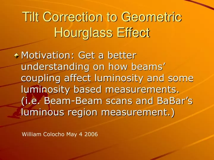
Tilt Correction to Geometric Hourglass Effect. Motivation: Get a better understanding on how beams’ coupling affect luminosity and some luminosity based measurements. (i.e. Beam-Beam scans and BaBar’s luminous region measurement.). William Colocho May 4 2006. Overview.

E N D
Tilt Correction to Geometric Hourglass Effect • Motivation: Get a better understanding on how beams’ coupling affect luminosity and some luminosity based measurements. (i.e. Beam-Beam scans and BaBar’s luminous region measurement.) William Colocho May 4 2006
Overview • Review hourglass effect and ‘zero bunch length’ tilt effect. • Describe how to combine these two. • Use optics model to extract S dependence of tilt near IP • Show simulation results. • Summary and questions.
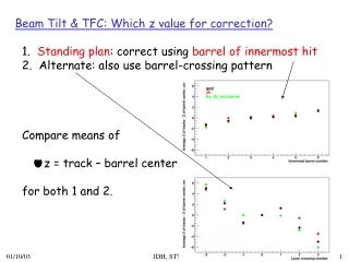
(“The Hourglass Reduction Factor for Asymmetric Colliders”, Miguel A. Furman, ABC-21/ESG- technote-161) Hourglass Luminosity Formula: Allows for s dependence: • This does not include tilt of beams due to coupling. • Tilt: Rotation angle of beam’s projection onto XY plane. • Twist: Tilt along the length of the bunch.
Zero Bunch Length Tilt Dependence (Luminosity degradation due to tilted and offset beams; B-Factory collider note; V. Ziemman, V.Kozanecki) 2-D Gaussian with centroid at the origin. 2X2 covariance matrix includes tilt angle. X’s are relative center position of one beam with respect to the other. Covariance matrix of the convolution of two Gaussians.
Method • Start with zero bunch length luminosity formula, including tilt dependence. • Then generate shape of luminous region (dL/ds) by allowing the covariance matrix (sigmas) to change with S, and use numerical integration to compute luminosity.
Covariance matrix S dependence One can use the zero bunch length result and include the bunch length dependence by allowing the covariance matrices of both beams to vary with s. The S dependence of the covariance matrix can be computed from the model’s calculation of the second moments of the beams’ distributions: (“Useful Formulae for General Coupled Linear Optics”; A. Wolski) Second moments’ quadratic fit
Simulation: (1) Beam-Beam scan using pep-optics design model run. Inputs: MAD LER Model “50x12.5 cm” MAD HER Model “50x12.5 cm”
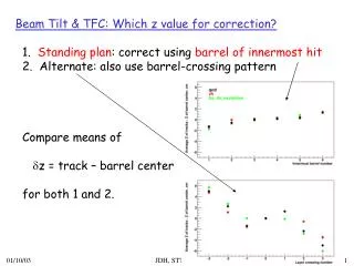
Non overlapping Y waists: both beams offset by 6mm in opposite directions. (Assumes waists move, but tilts do not move). Idea: Do Beam-Beam scans at different settings of the RF phase. Theta should be symmetric around zero.
Simulated: MIA LER model 3/16/2006 epsx = 27 nm [1] epsy = 5.0 nm [2] sigz+ = 11.3 mm [3] MIA HER model epsx = 49 nm [1] epsy = 2.5 nm [2] sigz- = 10.8 mm [4] Note how results vary depending on the model used. (April 21st MIA model not yet available).
Summary, Questions,Future work • Hourglass and Tilt effects can be combined using numerical integration with S dependence of the covariance matrix (beam envelope) extracted from the model. • Tilt measured with Beam-Beam scans may point to mistuning of the waist and/or tilt. • One could use these results to simulate a Tilt (Twist) vs. Luminosity scan. (Needs correct way to vary the Twist. i.e. How to vary the covariance matrices consistently).