Download

1 / 18
190 likes | 312 Views
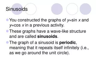
Sinusoids and Phasors. Objective of Lecture. Review how to determine whether a sinusoidal signal is lagging or leading a reference signal. Chapter 9.2 Fundamentals of Electric Circuits Explain phasor notation.

E N D
Objective of Lecture • Review how to determine whether a sinusoidal signal is lagging or leading a reference signal. • Chapter 9.2 Fundamentals of Electric Circuits • Explain phasor notation. • Describe the mathematical relationships between phasor notation and rectangular coordinates. • Chapter 9.3 Fundamentals of Electric Circuits
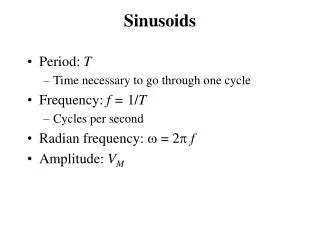
Sinusoidal Voltage where Vm is the amplitude of the sinusoid w is the angular frequency in radians/s f is the phase angle in degrees wt + f is the argument of the sinusoid
Period and Frequency T is the period of a sinusoid; units are seconds f is the frequency with units of Hz (cycles per second)
Phase between Cosine and Sine v1(t) = 6V sin(20t + 40o) v2(t) = -4V cos(20t + 20o) v1(t) = 6V cos(20t + 40o - 90o) = 6V cos(20t - 50o) v2(t) = 4V cos(20t + 20o - 180o) = 4V cos(20t - 160o) Phase angle between them is 110o and v1 leads v2
Alternatively v1(t) = 6V sin(20t + 40o) v2(t) = -4V cos(20t + 20o) v1(t) = 6V sin(20t + 40o) v2(t) = 4V sin(20t + 20o - 90o) = 4V sin(20t - 70o) Phase angle between them is 110o
Steps to Perform Before Comparing Angles between Signals • The comparison can only be done if the angular frequency of both signals are equal. • Express the sinusoidal signals as the same trig function (either all sines or cosines). • If the magnitude is negative, modify the angle in the trig function so that the magnitude becomes positive. • If there is more than 180o difference between the two signals that you are comparing, rewrite one of the trig functions • Subtract the two angles to determine the phase angle.
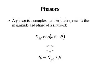
Phasor • A complex number that represents the amplitude and phase of a sinusoid jy Vm imaginary f x real
Real Number Line • If there is no imaginary component to the phasor, then the phasor lies on the real number line (x-axis). • Positive real numbers are written as: • Phasor notation • Rectangular coordinates • Negative real numbers are written as: • Phasor notation • Rectangular coordinates
Imaginary Number Line • If there is no real component to the phasor, then the phasor lies on the imaginary number line (y-axis). • Positive imaginary numbers are written as: • Phasor notation • Rectangular coordinates • Negative imaginary numbers are written as: • Phasor notation • Rectangular coordinates
Phasor Representation • Polar coordinates: • Rectangular coordinates • Sum of sines and cosines • Exponential form: Where the sinusoidal function is:
Sinusoid to Phasor Conversion • The sinusoid should be written as a cosine. • Amplitude or magnitude of the cosine should be positive. • This becomes the magnitude of the phasor • Angle should be between +180o and -180o. • This becomes the phase angle of the phasor. • Note that the frequency of the sinusoid is not included in the phasor notation. It must be provided elsewhere. • Phasors are commonly used in power systems, where the frequency is understood to be 60 Hz in the United States.
Sinusoid-Phasor Transformations Assumes Vm is positive and -180o ≤ f ≤ 180o
Phasor Notation Phasor notation is used when there are one or more ac power sources in a circuit. All of these power sources operate at the same single frequency. Used extensive in power systems because almost all of these systems operate at 60 Hz in the United States. Bold V and I are used to show that phasor notation is being used.
Summary • Phasor notation is used in circuits that have only ac power sources that operate at one frequency. • The frequency of operation is not included in the notation, but must be stated somewhere in the circuit description or schematic. • The steps to convert between sinusoidal functions and rectangular coordinates were described. • To express a phasor Pm ∕ f in rectangular coordinates (Re + jIm) can be performed using the following equations: