Introduction to MIPS Instruction Formats
Learn about R-type, I-type, and J-type instructions in the MIPS R2000/R3000 ISA, including formats, semantics, opcodes, and register usage. Understand how machine code encodes operations in this assembly language.

Introduction to MIPS Instruction Formats
E N D
Presentation Transcript
Instruction Format MIPS Instruction Set
Introduction • The MIPS R2000/R3000 ISA has fixed-width 32 bit instructions. • Fixed-width instructions are common for RISC processors because they make it easy to fetch instructions without having to decode. • These instructions must be stored at word-aligned addresses (i.e., addresses divisible by 4).The MIPS ISA instructions fall into three categories: R-type, I-type, and J-type. • Not all ISAs divide their instructions this neatly. • This is one reason to study MIPS as a first assembly language. • The format is simple.
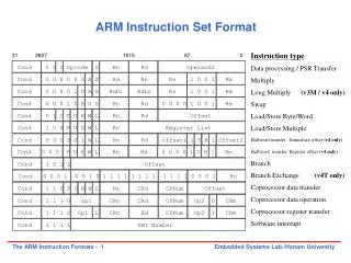
R-type • R-type instructions refer to register type instructions. • Of the three formats, the R-type is the most complex. • This is the format of the R-type instruction, when it is encoded in machine code.
Prototypical R-type add $rd, $rs, $rtwhere $rd refers to some registerd (d is shown as a variable, however, to use the instruction, you must put a number between 0 and 31, inclusive for d). $rs, $rt are also registers. Semantics of the instruction R[d] = R[s] + R[t] where the addition is signed addition. You will notice that the order of the registers in the instruction is the destination register ($rd), followed by the two source registers ($rs and $rt).
R-type instruction. • opcode (B31-26)Opcode is short for "operation code". The opcode is a binary encoding for the instruction. Opcodes are seen in all ISAs. In MIPS, there is an opcode for add. • The opcode in MIPS ISA is only 6 bits. Ordinarily, this means there are only 64 possible instructions. Even for a RISC ISA, which typically has few instructions, 64 is quite small. For R-type instructions, an additional 6 bits are used (B5-0) called the function. Thus, the 6 bits of the opcode and the 6 bits of the function specify the kind of instruction for R-type instructions. • rd (B25-21)This is the destination register. The destination register is the register where the result of the operation is stored. • rs (B20-16)This is the first source register. The source register is the register that holds one of the arguments of the operation. • rt (B15-11)This is the second source register. • shift amount (B10-6)The amount of bits to shift. Used in shift instructions. • function (B5-0)An additional 6 bits used to specify the operation, in addition to the opcode.
I-type instructions • I-type is short for "immediate type". The format of an I-type instuction looks like PrototypicalI-type add $rt, $rs, immedIn this case,$rt is the destination register, and $rs is the only source register. It is unusual that $rd is not used, and that $rd does not appear in bit positions B25-21 for both R-type and I-type instructions. Presumably, the designers of the MIPS ISA had their reasons for not making the destination register at a particular location for R-type and I-type.
Semantics of the addi instruction R[t] = R[s] + (IR15)16 IR15-0where IR refers to the instruction register, the register where the current instruction is stored. (IR15)16 means that bit B15 of the instruction register (which is the sign bit of the immediate value) is repeated 16 times. This is then followed by IR15-0, which is the 16 bits of the immediate value. Basically, the semantics says to sign-extend the immediate value to 32 bits, add it (using signed addition) to register R[s], and store the result in register $rt.
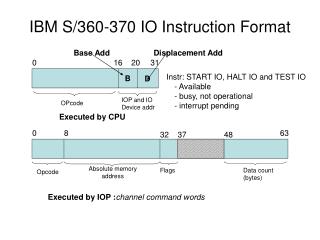
J-type instructions • J-type is short for "jump type". The format of an J-type instuction looks like: Prototypical I-type instruction j target The semantics j instruction (j means jump) where PC is the program counter, which stores the current address of the instruction being executed. You update the PC by using the upper 4 bits of the program counter, followed by the 26 bits of the target (which is the lower 26 bits of the instruction register), followed by two 0's, which creates a 32 bit address. The jump instruction will be explained in more detail in a future set of notes.
Summary MIPS instructions fall into three categories: R-type, I-type, and J-type. You should know how the bits are laid out (i.e., what the 6 parts of the R-type instruction are, and how many bits in each of the 6 parts). However, it's unnecessary to memorize opcodes.
Notes • PC-program counter provide the address of the next instruction to be execute • IM-Instruction Memory- hold and supply instruction given on address ALU-to compute the address of the next instruction • Register file is a collection of register in whereby any register can be read or written by specifying the number of the register in the file • Execute instruction or calculate the address, ALU operation • Data memory-access an operand in data memory • Write back-Which place the result back into the register file
Control Signal • Two ALUOp signals – ALUOp1 & ALUOp2 • Seven other signal • RegDst- Which field for write register • RegWrite-Write to register file • ALUSrc-source to second ALU input • PCSrc –Source to PC(PC+4 or target address) • MemRead-read input address/data to memory • MemWrite-write input address/data memory • MemToReg-source of write register port data input