Download

1 / 24
240 likes | 368 Views
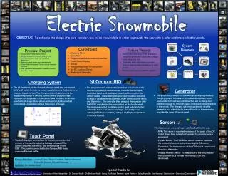
Electric Snowmobile Team. Table of Contents. Team members Starting point Definition of problem Solutions System Overview Key Components Monitoring system Charging System Generator System Design schedule Budget Thanks Questions. Project Team. Faculty Advisor . Students Members.

E N D
Table of Contents Team members Starting point Definition of problem Solutions System Overview Key Components Monitoring system Charging System Generator System Design schedule Budget Thanks Questions
Project Team Faculty Advisor Students Members Patrick Hingston Roger Gauthier Lindsey Chiron Dr.Kraft Parker McDonnell Michael Swanson Bryce Kelley
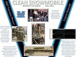
Starting Point Building off Electric Snowmobile Built last year Comprised of 20KW electric motor Motor mounted on solid aluminum frame 96V Battery Bank (eight 12V Lead Acid Batteries) Batteries stored under seat compartment Pulse Width Modulation Circuit controls transistor ON/OFF IGBT (Insulated Gate Bipolar Transistor) controls armature current Zero to max RPM motor control using PWM Direct drive transmission requires no clutch 20KW electric motor Zero To Max RPM PWM Circuit 96v Battery Bank
Definition of Problem • Current Issues • Lack of real time system monitoring • No user heads up display • Nonexistent charging system • No emergency backup power • Lack of safety features (GPS location, IGBT temperature monitoring, Battery State of Charge) • Lack of Headlights • Drive shaft held together with cotter pin • Weak drive shaft • Loud engine whine
Touch Panel Proposed Solutions • System To Be Implemented • Sensors measuring system vitals • Monitoring System using CompactRIO • Integrated GPS unit • Smart Battery Charger • Emergency Generator system • User heads up display • HID headlights • Noise reduction materials • Hardened steel drive shaft/tightened drive chain Compact RIO GPS Unit Sensors Charging Circuit DC Motor 120V Generator Charging System
System Overview PWM Circuit Touch Panel Compact RIO Sensors Generator DC Motor Diagram Legend High Power Charging System Battery Bank Output Signal Bidirectional Signal
CompactRIO • Device Description • Donated by National Instruments • Small, rugged embedded control and data acquisition • Embedded real-time processor built into chassis (400MHz Freescale) • Powered by National Instruments Labview (Graphical programming language) • Hot-swappable industrial I/O modules with built in signal conditioning for direct connection to a variety of sensors and actuators • Extremely rugged, -40 to 70 °C (-40 to 158 °F) operating temperature • Up to 2,300Vrms isolation • 50g Shock Rating • Dual 9 to 35 VDC supply input low power consumption (7 to 10W typical) • (7.07 X 3.47 X3.47 in.) and weighs 3.47 lb • HMI connection for interface with • touch panel module Unit price$2500
Touch Panel • Device Description • Donated by National Instruments • 5.3’’ touch panel display • Max power Consumption of 20W • 18-32 VDC power input • -20 to 70 °C (-4 to 158 °F) temperature operation • 320 X 240 Pixels (256 Colors) • 416 MHz Intel XScale processor running Windows CE • Ethernet connection for communication with • CompactRIO Unit price$809
Generator • Device Description • 2100 Watts of AC Power • 125-cc, 4 Stroke air cooled engine (no need to mix oil/gas) • 62dB at 7 meters (23 feet) • 1.5 gallon fuel tank • 2.5 hour runtime at full load • Pull start • 22 x 20 x 11 inches • 62 pounds • Economy mode reduces noise and fuel • consumption Unit price $498
Beginnings of Charging System • Device Description • Step down transformer • 120v to 14.5v (RMS) • Full Wave rectifier • Large capacitor reduces • AC ripple • Voltage comparator • provides charging status • ON/OFF switch • LED lights show status • of batteries • Fuse protect batteries • from over current • Provides constant DC • voltage to batteries Estimated price +$300
Temperature Reading Instantaneous Current and Voltage IGBT Thermistor Magnetic Pickup or Optical Encoder Pulses Monitoring System 20KW DC Motor Pulse Accumulator Analog Port PWM Signal Ethernet Connection Analog Port NI Compact Rio 2KW Generator Battery Monitor System Output GPS Position, heading, velocity serial data 96v Battery Bank Garmin GPS 18 NI Touch panel Module
System Monitoring The CompactRIO will be used to monitor a variety of the snowmobiles vitals Using analog I/O DAQ modules • Parts List • NI Compact Rio ($2500) • NI touch panel ($809) • Honeywell Magnetic Pickup Sensor ($10) • Garmin 18 ($60) • Thermocouple ($5) • Headlights($10) • Capacitors (Cheap) • Resistors (Cheap) • Relays ($50) • Transistors (Cheap) • Measurements • Motor current (Current) • Motor RPM (frequency) • PWM signal (Voltage vs time) • Duty Cycle of PWM signal • Distance Traveled • Battery Level (Voltage) • Global Position (Serial data) • Generator Power output (voltage) • Outside Temperature (thermocouple voltage) • IGBT temperature level (thermistor voltage) Estimated Total $150
Battery Monitoring To determine the state of charge per battery we will be measuring the voltage across each batteries terminal The voltage measured can be used to determine the percentage of charge present according to the figure The NI CompactRIO analog I/O port will Be used to measure this voltage, determine the percent charge and display this information in a bar chart for the user to see
Sensor Voltages RPM and Other measurements To measure the RPM of the DC motor a magnetic toothed gear will be mounted on the drive shaft. A Honeywell magnetic pickup sensor will generate a pulse each time the magnet passes by CompactRIO These pulses will be sent back to the counter module of the CompactRIO The frequency of these pulses will be determined and effectively RPM can be found using the relationship RPM = Fp The other measurements to be taken will be comprised of voltages that can be easily measured with the analog DAQ module on the CompactRIO DC Motor
120V Outlet FW Rectifier Transformer Relay Circuitry Fuse Ripple Remover Charging System Diagram Legend Battery Bank High Voltage Low Voltage High Current
Charging System The charging system will be used to recharge the snowmobiles batteries quickly and safely • Parts List • High powered relays ($50 a piece) • Transformer ($30) • Diodes (Cheap) • Capacitors (Cheap) • Resistors (Cheap) • Green, Yellow, Red LEDs (Cheap) • Operational Amplifiers (Cheap) • Power Cables ($10) • High Powered Switches ($10) Estimated Total $300
Diagram Legend 120V Generator CompactRIO • Control Signal • Signal Voltage High Voltage High Current Battery Bank Charging Circuit Generator System DC Motor
Generator system The generator system will be used to Provide emergency power to the batteries in the event of discharged batteries • Parts List • Honeywell 2100 Watt Generator ($498) • Power Cables ($10) • Welded shelf frame (Donated) • Gasoline hopper ($20) • High powered Relay ($50) With a few tweaks the generator Should be able to directly interface with the input of the charging system Estimated Total $580
Design Schedule Fall Semester
Design Schedule Spring Semester
Thank You Dr. Gordon Kraft & Dr. Barbara Kraft Lesley Yu of National Instruments Stephen Doran, Luke Varitek, Bryce Kelley