Download
1 / 18
190 likes | 294 Views
Explore the impact of mirror imperfections on beam divergence, brightness, and intensity in LCLS X-ray experiments. Learn about slope errors, mirror roughness, and mirror length optimization for different X-ray wavelengths.

E N D
Effects of LCLS X-Ray Mirrors John Arthur Presenting work by Peter Stefan and Mike Pivovaroff
Offset mirrors in the FEE Upstream of all LCLS experiments Will remove high-energy background radiation FEL radiation reflected (>95%) SiC 1.5mrad SiC 1.5mrad 24mm offset Background from high harmonics and Bremsstrahlung not reflected
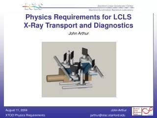
X-ray mirror locations in FEE Soft x-ray mirrors Hard x-ray mirrors ~14m
NEH AMO SXR X-ray pump-probe soft x-ray line hard x-ray line Hutch 1 Hutch 2 Hutch 3
FEH XPCS Coherent x-ray imaging High energy density science Hutch 4 Hutch 5 Hutch 6
Effects of Mirror Imperfections • Imperfections happen on all length scales • Power Spectral Density function (PSD) typically shows fractal power law behavior (with smaller errors at shorter wavelengths) • Roughness • Errors on x-ray wavelength scale • Cause scatter far out of direct beam • Slope errors • Errors on micron scale (larger than l, but small compared to beam footprint) • Cause broadening of beam divergence
Beam profile downstream of imperfect mirror Broadening due to slope error Beam distorted by mirror Scatter due to roughness Ideal beam
For the LCLS, mirror roughness should not be a big problem. Realistic values of roughness will remove <5% of the beam intensity from the central spot. Slope errors will broaden the beam and reduce its brightness. This is our major concern.
We considered three cases for slope error: rms = 1 µrad, 0.5µrad, and 0.1µrad The state of the art for 1m-length mirrors: 1 µrad mirrors are readily available from several vendors 0.5 µrad mirrors are probably available, for a price 0.1 µrad mirrors may not be available today, but will be within a few years
Note: shorter mirrors are better (World record: 0.01µrad rms, for a 100mm-long mirror) The 1m length of the LCLS hard x-ray mirrors is driven by the desire to reflect 24keV radiation, and the desire to accept all of the beam at 2 keV, and still not hit the end regions of the mirror. Also note: the soft x-ray mirrors are short. They operate at a steeper angle, so a length of only 100-200mm is needed.
NEH Hutch 1 z=117.1m (distance from end of undulator) Using short B4C mirrors at 15mrad incidence 2keV 800eV 2keV 800eV 800eV 2keV 2keV 800eV
NEH Hutch 2 z=128.1m Using short B4C mirrors at 15mrad incidence 800eV 2keV 800eV 2keV 800eV 800eV 2keV 2keV
NEH Hutch 3 z=138.8m Using 1m SiC mirrors at 1.3mrad incidence 8keV 2keV 8keV 8keV 8keV 2keV 2keV 2keV
FEH Hutch 4 z=364.9m Using 1m SiC mirrors at 1.3mrad incidence 2keV 8keV 2keV 8keV 2keV 8keV 2keV 8keV
FEH Hutch 5 z=385.5m Using 1m SiC mirrors at 1.3mrad incidence 2keV 8keV 8keV 8keV 2keV 2keV 8keV 2keV
FEH Hutch 6 z= 406.1m Using 1m SiC mirrors at 1.3mrad incidence 2keV 8keV 2keV 8keV 8keV 8keV 2keV 2keV