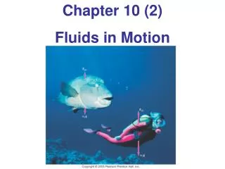
Chapter 15B - Fluids in Motion
Chapter 15B - Fluids in Motion. A PowerPoint Presentation by Paul E. Tippens, Professor of Physics Southern Polytechnic State University. © 2007. Fluid Motion.


Chapter 15B - Fluids in Motion
E N D
Presentation Transcript
Chapter 15B - Fluids in Motion A PowerPoint Presentation by Paul E. Tippens, Professor of Physics Southern Polytechnic State University © 2007
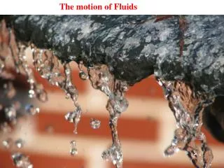
Fluid Motion The lower falls at Yellowstone National Park: the water at the top of the falls passes through a narrow slot, causing the velocity to increase at that point. In this chapter, we will study the physics of fluids in motion. Paul E. Tippens
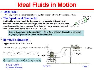
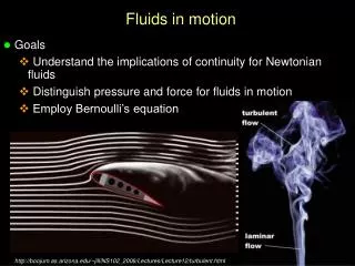
Objectives: After completing this module, you should be able to: • Define the rate of flow for a fluid and solve problems using velocity and cross-section. • Write and apply Bernoulli’s equation for the general case and apply for (a) a fluid at rest, (b) a fluid at constant pressure, and (c) flow through a horizontal pipe.
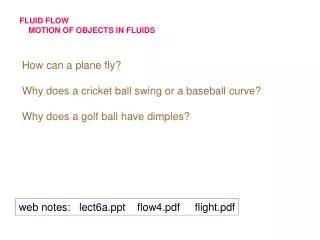
All fluids are assumed in this treatment to exhibit streamline flow. Fluids in Motion • Streamline flowis the motion of a fluid in which every particle in the fluid follows the same path past a particular point as that followed by previous particles.
Assumptions for Fluid Flow: • All fluids move with streamline flow. • The fluids are incompressible. • There is no internal friction. Streamline flow Turbulent flow
The volume Vof fluid is given by the product of area A and vt: vt A Volume = A(vt) Rate of flow = velocity x area Rate of Flow The rate of flow R is defined as the volume Vof a fluid that passes a certain cross-section A per unit of time t.
A1 R = A1v1 = A2v2 A2 v2 v1 v2 Constant Rate of Flow For an incompressible, frictionless fluid, the velocity increases when the cross-section decreases:
Example 1: Water flows through a rubber hose 2 cm in diameter at a velocity of 4 m/s. What must be the diameter of the nozzle in order that the water emerge at 16 m/s? The area is proportional to the square of diameter, so: d2 = 0.894 cm
Example 1 (Cont.): Water flows through a rubber hose 2 cm in diameter at a velocity of 4 m/s. What is the rate of flow in m3/min? R1 = 0.00126 m3/s R1 = 0.0754 m3/min
Problem Strategy for Rate of Flow: • Read, draw, and label given information. • The rate of flow R is volume per unit time. • When cross-section changes, R is constant. • Be sure to use consistent units for area and velocity.
Problem Strategy (Continued): • Since the area A of a pipe is proportional to its diameter d, a more useful equation is: • The units of area, velocity, or diameter chosen for one section of pipe must be consistent with those used for any other section of pipe.
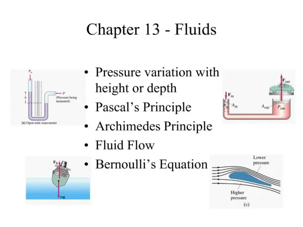
h A C B The Venturi Meter The higher velocity in the constriction B causes a difference of pressure between points A and B. PA - PB = rgh
Examples of the Venturi Effect Demonstrations of the Venturi Principle The increase in air velocity produces a difference of pressure that exerts the forces shown.
A2 P2 A1 P1 A2 Volume V P2 A1 h P1 F1 Note differences in pressure DP and area DA Work in Moving a Volume of Fluid , F2 Fluid is raised to a height h.
F2 = P2A2 A2 v1 v2 F1 = P1A1 s2 A1 h2 s1 h1 Net Work = P1V - P2V = (P1 - P2) V Work on a Fluid (Cont.) Net work done on fluid is sum of work done by input force Fi less the work done by resisting force F2,as shown in figure.
F2 = P2A2 A2 v1 v2 F1 = P1A1 s2 A1 h2 s1 h1 Conservation of Energy Kinetic Energy K: Potential Energy U: also Net Work = DK + DU Net Work = (P1 - P2)V
v2 v1 Bernoulli’s Theorem: h2 h1 Conservation of Energy Divide by V, recall that density r = m/V, then simplify:
v1 v2 r h1 = h2 h Horizontal Pipe Bernoulli’s Theorem (Horizontal Pipe): Horizontal Pipe (h1 = h2) Now, since the difference in pressure DP = rgh,
v2 r v1 = 4 m/s h= 6 cm h Example 3:Water flowing at 4 m/s passes through a Venturi tube as shown. If h = 12 cm, what is the velocity of the water in the constriction? Bernoulli’s Equation (h1 = h2) Cancel r, then clear fractions: 2gh = v22 - v12 v2 = 4.28m/s Note that density is not a factor.
r = 1000 kg/m3 h Bernoulli’s Theorem for Fluids at Rest. For many situations, the fluid remains at rest so that v1 and v2are zero. In such cases we have: P1 - P2 = rgh2 - rgh1 DP = rg(h2 - h1) This is the same relation seen earlier for finding the pressure P at a given depth h = (h2 - h1) in a fluid.
h h2 h1 Torricelli’s theorem: Torricelli’s Theorem When there is no change of pressure, P1 = P2. Consider right figure. If surface v2 0 and P1= P2 and v1 = v we have: v2 0
v v v Torricelli’s theorem: Interesting Example of Torricelli’s Theorem: • Discharge velocity increases with depth. • Maximum range is in the middle. • Holes equidistant above and below midpoint will have same horizontal range.
h Torricelli’s theorem: Example 4:A dam springs a leak at a point 20 m below the surface. What is the emergent velocity? Given: h = 20 m g = 9.8 m/s2 v = 19.8m/s2
Strategies for Bernoulli’s Equation: • Read, draw, and label a rough sketch with givens. • The height h of a fluid is from a common reference point to the center of mass of the fluid. • In Bernoulli’s equation, the density r is mass density and the appropriate units are kg/m3. • Write Bernoulli’s equation for the problem and simplify by eliminating those factors that do not change.
r = 1000 kg/m3 h Strategies (Continued) • For a stationary fluid, v1 = v2 and we have: DP = rg(h2 - h1) • For a horizontal pipe, h1 = h2and we obtain:
Strategies (Continued) • For no change in pressure, P1 = P2 and we have: Torricelli’s Theorem
B R=30 L/s 8 m A vA = 1.49 m/s vB = 3.82 m/s General Example: Water flows through the pipe at the rate of 30 L/s. The absolute pressure at point A is 200 kPa, and the pointBis 8 m higher than point A. The lower section of pipe has a diameter of 16 cm and the upper section narrows to a diameter of 10 cm. Find the velocities of the stream at points Aand B. R = 30 L/s = 0.030 m3/s AA = (0.08 m)2 = 0.0201 m3 AB = (0.05 m)2 = 0.00785 m3
Given: vA = 1.49 m/s vB = 3.82 m/s PA = 200 kPa hB - hA = 8 m 0 B R=30 L/s 8 m A General Example (Cont.):Next find the absolute pressure at Point B. Consider the height hA = 0 for reference purposes. PA + rghA +½rvA2 = PB + rghB + ½rvB2 PB = PA + ½rvA2 - rghB - ½rvB2 PB = 200,000 Pa + 1113 Pa –78,400 Pa – 7296 Pa • PB = 200,000Pa + ½(1000 kg/m3)(1.49 m/s)2 • – (1000 kg/m3)(9.8 m/s2)(8 m) - ½(1000 kg/m3)(3.82 m/s)2 PB = 115 kPa
Streamline Fluid Flow in Pipe: Fluid at Rest: Horizontal Pipe (h1 = h2) PA - PB = rgh Bernoulli’s Theorem: Torricelli’s theorem: Summary
Summary: Bernoulli’s Theorem • Read, draw, and label a rough sketch with givens. • The height hof a fluid is from a common reference point to the center of mass of the fluid. • In Bernoulli’s equation, the density r is mass density and the appropriate units are kg/m3. • Write Bernoulli’s equation for the problem and simplify by eliminating those factors that do not change.