Download

1 / 52
540 likes | 671 Views
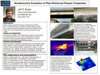
Learn about nondestructive evaluation methods like liquid penetrant, ultrasonic testing, magnetic particle inspection, and eddy current testing. Understand the principles and applications of these techniques in detecting surface and subsurface defects in materials.

E N D
Nondestructive evaluation (NDE) Topic 7
Reading assignment • Notes on Nondestructive Evaluation in the course website. • Sec. 8.2, 8.3 and 8.4, William Callister, Materials Science and Engineering, 6th Ed.
Conventional NDE mthods • Liquid penetrant inspection • Ultrasonic inspection • Acoustic emission • Magnetic particle inspection • Eddy current testing • X-radiography
Liquid penetrant inspection • For detection of surface defects • Inexpensive and convenient • Largely used on nonmagnetic materials for which magnetic particle inspection is not possible. • Unable to inspect subsurface flaws. • Loss of resolution on porous materials.
Penetrant High-visibility liquid
Liquid penetrant inspection method 1. Apply a penetrant to the surface. 2. Pull penetrant to the surface crack by capillary action. 3. Remove excessive penetrant. 4. Extract some penetrant to the surface.
Audible frequency range 20 – 20,000 Hz
Ultrasonic inspection • Ultrasonic wave has higher frequency than audible sound. • Typical frequency from 25 to 100,000 MHz. • Method: Send an ultrasonic wave (from a piezoelectric transducer) through the material (via a transmitting medium) and measure the intensity of the reflected or transmitted wave, and the time it takes for the wave to be detected.
Ultrasonic inspection • Ultrasonic wave has higher frequency than audible sound. • Typical frequency from 25 to 100,000 MHz. • Method: Send an ultrasonic wave through the material and measure the intensity of the reflected or transmitted wave, and the time it takes for the wave to be detected.
Through-transmission configuration (two transducers)
Pulse-echo mode Single transducer connected to the material by water (an acoustic coupling medium)
Attenuation of ultrasonic wave upon traveling through the material. One cycle means traveling from the front surface to the back surface and then to the front surface.
Acoustic emission (AE) testing • Process of developing defects such as cracks causes the emission of ultrasonic waves. • AE measures the ultrasonic waves produced by defects in a material in response to an applied stress. • Transducer serves as receiver, not ultrasonic emitter.
A fiber composite experiencing delamination during loading and friction between delaminated surfaces during unloading.
AE applications • Failure prevention (warning of impending failure; rate of AE events rising sharply just prior to failure) • Locating defects
Magnetic particle inspection • Limited to magnetic materials. • Inexpensive and convenient.
Magnetic particle inspection method • Magnetic flux lines in a ferromagnetic or ferrimagnetic material (resulting from the application of a magnetic field) are distorted around a defect. • Distortion causes magnetic flux lines to protrude from the surface at the location of the surface crack. This is known as “field leakage”. • Field leakage attracts magnetic particles (Fe or Fe3O4) that are applied to the surface. • Subsurface cracks near the surface can also be detected. • Applied magnetic field is preferably perpendicular to the length of the defect.
Distortion of the magnetic flux lines due to a surface crack in a magnetic material
Distortion of the magnetic flux lines due to a subsurface defect
Little distortion of the magnetic flux lines when the length of the defect is parallel to the applied magnetic field
A time-varying magnetic field induces a current in a copper ring. Faraday’s Law
Eddy current An eddy current is an electric current induced in an electrically conductive material due to an applied time-varying magnetic field. Due to Faraday’s law, a voltage is generated in a conductor loop when the magnetic flux through the loop is changed. The eddy current is in a direction such that the magnetic field it generates opposes the applied magnetic field.
An axial magnetic field generated by a circumferential electric current A circumferential magnetic field generated by an axial electric current
Generation of an eddy current by an applied magnetic field A cylindrical sample A flat sample
Eddy current testing method The impedance of an inspection coil is affected by the presence of an adjacent, electrically conductive test piece, in which eddy current has been induced by the coil. By varying the frequency, the method can be used for both surface and subsurface flaws.
Eddy current testing limitations • Limited to electrically conductive materials. • Qualitative
X-radiography • Good for detecting internal defects. • Method: Send x-rays through the material and detect the transmitted x-ray image using a photographic film.
X-ray absorption (not diffraction)
Fractography • Fracture surface examination • Different from metallography
Introduction Broken cabin bolt from an elevator
An oil tanker that fractured in a brittle manner by crack propagation around its girth Introduction
Highly ductile fracture Moderately ductile fracture Brittle fracture
Irregular & fibrous appearance Ductile Fracture Ductile fracture Cup-and-cone fracture in aluminum
Stages in cup-and-cone fracture Small cavity formation Initial necking Coalescence of cavities to form a crack Crack propagation Final shear failure at a 45 degree angle
Ductile Fracture • moderately ductile: most common, moderate necking before fracture. • Stages: i) microvoid formation, ii) microvoid coalescence leading to “microcrack” formation normal to the applied stress, iii) rapid crack propagation at about 45° to tensile axis (max)). • cup and cone fracture.
Brittle fracture in mild steel Brittle Fracture
Brittle fracture • In hard & fine-grained metals, there will be no discernible pattern. • In amorphous materials, the fracture surface is relatively shiny & smooth. • In most brittle crystalline materials crack propagates along specific crystallographic planes cleavage.
Brittle Fracture Scanning electron micrograph of ductile cast iron showing a transgranular fracture surface
Brittle Fracture Scanning electron micrograph showing an intergranular fracture surface
Brittle fracture • The cleavage fracture is transgranular (transcrystalline) • Macroscopically the fracture surface has a grainy or faceted texture due to changes in orientration of cleavage plains from grain to grain. • Intergranular fracture crack propagates along grain boundaries. This shows evidence of a weaker material, embrittlement.
Brittle fracture • Fracture with no obvious deformation, fast crack growth normal to the applied . • Relative flat fracture surface. • Some steels may show V-shaped “chevron” markings that point back to crack initiation.
Brittle Fracture Photograph showing V-shaped “chevron” markings characteristic of brittle fracture