Database Design
Database Design. HIMA 4160 Fall 2009. House Keeping. Assignment 4 due tonight Assignment 5 due next Monday. . Agenda. Database Concepts Entity Relational Diagram (ERD). Database == Data + Base. Transaction. Storage. Database: Definition. A collection of data that: is organized

Database Design
E N D
Presentation Transcript
Database Design HIMA 4160 Fall 2009
House Keeping • Assignment 4 due tonight • Assignment 5 due next Monday.
Agenda • Database Concepts • Entity Relational Diagram (ERD)
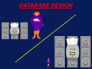
Database == Data + Base Transaction Storage
Database: Definition • A collection of data that: • is organized • usually computer-based • represents repetitive information implicitly • primarily for transaction • supports retrieval
Is paper medical record a database? • Yes • No • No opinion
Is Excel a database system? • Yes • No • No Opinion
Database Management System (DBMS) • A computer program for the purposes of managing databases. • Is the basis for many applications (e.g., Electronic Health Records, Personal Health Records). • A DBMS can host many databases • A database can be implemented in many different DBMS systems.
Data Modeling • Before you implement a database, you need to design the database • Data modeling is a systematic way to help you design the database. • Map/simplify the real world to database schema/structure.
Why Data Modeling? • Power and flexibility of database depend on data model • Database is the realization of data model • Evaluation of commercial products • Communicating with vendors and IT staff • Building your own databases
Database Analysis • Determine User Requirements • Develop Data Models • “A conceptual data model is one that represents data from the viewpoint of the user, independent of any technology that will be used to implement the model.” • A database has two parts • Schema • Data
Stages of Data Modeling • Conceptual Model • E-R diagram • Logical Model • Relational Model • Physical Model • Database management
Database Modeling Conceptual Logical Physical Real World E-R Diagram Relational Model DBMS
Introduction • Entity Relationship Modelling (ERM) • A technique used to analyze & model the data in organizations • Using diagram to represent entities and relationship of components in a system. • Supported by modern DBMS system. • De facto tool for database design
The Importance of Data Modeling • Characteristics captured during data modeling • crucial in design of databases, programs, other items • facts and rules essential in assuring data integrity • Data are the most complex aspects of the modern organization • Data are determined by the business rules. • Need to avoid scope creeps • Data tend to be more stable than the business processes that use the data
Definitions • Entity • an aggregation of a number of data elements • each data element is an attribute of the entity • Relationship • an association between two or more entities that is of particular interest
Background • Introduced by Peter Chen in ’75 • “The Entity-Relationship Model – Toward a Unified View of Data”, ACM Transactions on Database Systems, Vol. 1, No. 1, March 1976, Pages 9 - 36 • now widely used in commercial database.
Why use ER Diagrams ? • provides a global quick reference to an organization’s data structures. • can be used individually to design an Information System’s (IS) data structure. • offers a basis of consequential database design and development.
ERD Development Process • Identify the entities • Determine the attributes for each entity • Select the identifier for each entity • Establish the relationships between the entities • Draw an entity model • Test the relationships and the keys
Entities • Person, place, object, event, or concept … • in the user environment • about which the organization wishes to maintain data • Entity type • collection of entities that share common properties or characteristics • CAPITAL LETTERS • Entity instance • single occurrence of an entity type ENTITY
A Simple Example • STUDENTs attend COURSEs that consist of many SUBJECTs. • A single SUBJECT (i.e. English) can be studied in many different COURSEs. • Each STUDENT may only attend one COURSE.
Identify the entities Any physical object, event, or abstract concept that we can record facts about. Rule of thumbs: • Look for nouns • Not all nouns are entities • Some of them are attributes
Identify Entities A football team has coaches, players, trainers and other assistants. Coach’s roles include head coach, defense and offence coordinators, quarterback coaches, etc. Football players can play different positions like quarterback, running backs, receivers etc. Rule of thumbs: • Look for nouns • Not all nouns are entities • Some of them are attributes
Identify Entities (my answers) • Coach • Player • Trainer • Assistants • Roles • Positions
Attributes • Property or characteristic of an entity type that is of interest to the organization • initial capital letter followed by lowercase letters • underscore instead of space (first_name) • Simple or Composite? • composite has component parts • will users need to refer to those individual components? • Single-valued or Multivalued? • Stored or Derived? Name Number PLAYER
Determine the Attributes • Every Entity has attributes. • Attributes are characteristics that allow us to classify/describe an entity • e.g., entity STUDENT has the attributes: • student number • name • date of birth • course number
Identifier [Attribute] • “An identifier is an attribute (or combination of attributes) that uniquely identifies individual instances of an entity type.” • atomic or composite • Criteria • will not change its value • never null • unique SS# Name Number PLAYER
Key Attributes • Certain attributes identify particular facts within an entity, these are known as KEY attributes. • The different types of KEY attribute are: • Primary Key • Composite Primary Key • Foreign Key
Key Definitions • Primary Key: • One attribute whose value can uniquely identify a complete record (one row of data) within an entity. • Composite Primary Key • A primary key that consists of two or more attribute within an entity. • Foreign Key • A copy of a primary key that exists in another entity for the purpose of forming a relationship between the entities involved.
COURSE ER Diagram Notations • Every entity diagram consists of the following components: Entity (labelled box) Relationship line
Degrees of a Relationship One-to-one (1:1) 1 1 • WOMAN • MAN One-to-many (1:n) 1 M • ORDER • CUSTOMER Many-to-many (n:m) M M • SUBJECT • COURSE NOTE: Every many to many relationship consists of two one to many relationships working in opposite directions
Notation of Cordiality (Degree of relationship) One-to-one (1:1) • WOMAN • MAN One-to-many (1:n) • ORDER • CUSTOMER Many-to-many (n:m) • Subject • Course
CAR Notation for Optional Participation 1 M PERSON A person can own no or several cars. A car doesn’t have to be owned by a person, but if it is, it is owned by only one person. 1 optional relationship
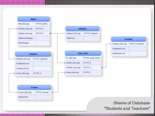
A Sample Four Entities ER Diagram SUBJECTS STUDENTS COURSES PROFESSORS A Student Record Entity Diagram
Exercise • One patient can see several doctors. One doctors can see many patients. A patient may not see a doctor at all
Exercise • A nurse is assigned to manage an exam room.
Exercise • A patient must have a insurance and a insurance company can have many patients as their customer.
Exercise (complex one) • Draw an E-R diagram to represent the data schema of a physician office. The entities included are physicians, patients, insurance companies, lab, medications etc.
ER Diagram Summary • Identify the entities • Determine the attributes for each entity • Select the primary key for each entity • Establish the relationships between the entities • Draw an entity model
Conceptual Design BED PATIENTS
Conceptual Design DOCTORS PATIENTS
DOCTORS PATIENTS
Conceptual Design DOCTORS PATIENTS
Conceptual Design • DOCTORS • Doctor_ID • Doctor_lname • Doctor_fname • Doctor_mi • Doctor_specialty • Doctor_address • Doctor_phone • Doctor_email • PATIENTS • Patient_ID • Patient_lname • Patient_fname • Patient_mi • Patient_address • Patient_phone • Patient_email
Logical Model • Entities tables • Relationship keys (primary and foreign) • Many to many two one to many relationship with an associate entity in the middle • Normalization