Download
1 / 18
200 likes | 478 Views
IEEE 802.1q - VLANs. Nick Poorman. dot1q. IEEE standard can be found here: http://standards.ieee.org/getieee802/802.1.html RFC 3069 can be found here: http://www.faqs.org/rfcs/rfc3069.html. dot1q.

E N D
IEEE 802.1q - VLANs Nick Poorman
dot1q • IEEE standard can be found here: http://standards.ieee.org/getieee802/802.1.html • RFC 3069 can be found here: http://www.faqs.org/rfcs/rfc3069.html
dot1q • VLAN Tagging - A networking standard written by the IEEE 802.1 workgroup allowing multiple bridged networks to transparently share the same physical link without leakage of information between networks.
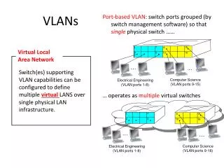
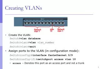
Difference between a subnet and a VLAN? • A subnet(Layer 3): part of the IP address space, eg 192.168.1.0/255.255.255.0, 10.1.1.1/255.255.255.0 (10.x.x.x networks normally have 255.0.0.0 as the subnet) • VLAN(Layer 2): A “Virtual” LAN is a section of ports on a/many switch[es] that act as if they are their own separate LAN – can have many different IP subnets as VLANs are not based on IP’s.
Frame Format • Does not actually encapsulate the original frame. Instead adds a 32-bit field between the source MAC address and the EtherType/Length fields of the original frame. • Double/Tripple tagging is allowed. Exploit? • Tag Protocol Identifier (TPID): a 16-bit field set to a value of 0x8100 in order to identify the frame as an IEEE 802.1Q-tagged frame. This field is located at the same position as the EtherType/Size field in untagged frames, and is thus used to distinguish the frame from untagged frames. • Priority Code Point (PCP): a 3-bit field which refers to the IEEE 802.1p priority. It indicates the frame priority level from 0 (lowest) to 7 (highest), which can be used to prioritize different classes of traffic (voice, video, data, etc). • Canonical Format Indicator (CFI): a 1-bit field. If the value of this field is 1, the MAC address is in non-canonical format. If the value is 0, the MAC address is in canonical format. It is always set to zero for Ethernet switches. CFI is used for compatibility between Ethernet and Token Ring networks. If a frame received at an Ethernet port has a CFI set to 1, then that frame should not be bridged to an untagged port. • VLAN Identifier (VID): a 12-bit field specifying the VLAN to which the frame belongs. A value of 0 means that the frame doesn't belong to any VLAN; in this case the 802.1Q tag specifies only a priority and is referred to as a priority tag. The hexadecimal value of 0xFFF is reserved. All other values may be used as VLAN identifiers, allowing up to 4094 VLANs. On bridges, VLAN 1 is often reserved for management. • http://en.wikipedia.org/wiki/IEEE_802.1Q
Multiple Spanning Tree Protocol (MSTP) • Originally defined in IEEE 802.1s • Merged into IEEE 802.1q-2003 • Layer 2 protocol used to prevent bridge loops in the network topology • Select the root bridge • Determine the least costs paths to the root • Disable all other paths to the root • Per-VLAN MSTP configures a separate Spanning Tree for each VLAN group and blocks all but one of the possible alternate paths within each Spanning Tree
802.1q/Cisco ISL Trunking Protocol • Allows multiple VLANs to span multiple switches
Using VLANs for Security ….Good or Bad? • VLANs were not intended to be used for isolation, a founding principle of security, however they are being used for just that. • There are inherent vulnerabilities with using VLANs for isolation. • http://www.spirit.com/Network/net0103.html
VLAN Exploits • Packets hop to a different VLAN • For example: Systems have established TCP/IP communications on the same VLAN, then the switch gets configured so that one system's port now belongs to a different VLAN. Communications continues between the two systems because each has the MAC address of the other in its ARP cache, and the bridge knows which destination MAC address gets directed to which port. • Scapy: a script-kiddie program to test the 802.1q network for vulnerabilities. • http://www.darknet.org.uk/2007/05/scapy-interactive-network-packet-manipulation/-Scapy
VLAN Exploits • Multiple tags can be used to route over trunks • Layer 3 routing device can be used to route packets from one VLAN to the next. This causes problems with our isolation principle.
Experiment Isolation in a Secure Cluster Testbed • http://www.usenix.org/event/cset08/tech/full_papers/lahey/lahey_html/ • After reading this white paper on the DETER cluster testbed (modeled after Utah’s Emulab), the idea of a “Tagger” being used as a means of isolating experiments into their own network, seemed intriguing. • Decided to use it as a means of extreme isolation for each node on the network to protect themselves from each other as well as the outside world.
Solution? • The Tagger. • In order to use VLANs as a means of secure isolation there must be a check to verify a packet passing through the network, is not malicious. This is relatively simple to do by having a “bridge device” sitting in front of the switch. • This server is responsible for doing Layer 2 tagging of the VLAN ID. • By keeping a static table of MAC address to VLAN ID the tagging server and the switch can do low level packet filtering.
The Tagging Server • By keeping a static table of MAC address to VLAN ID mappings we can tag packets before they enter the switch with the appropriate VLAN ID as well as filter packets coming from the switch on the trunk port, that have been spoofed with another machines MAC address. • As a packet enters the tagging server the destination MAC address is inspected in the packet and looked up in the table. • If a corresponding VLAN ID is found for the destination MAC, the packet will be tagged with the VLAN ID information and will be forwarded onto the switch. If a corresponding VLAN ID is not found in the table the packet will be dropped. • (ebtables can do the filtering) – essentially IPTables for layer 2
The Switch • A packet entering the switch on the trunk port will have its MAC header inspected for the destination address. • If the MAC address and the VLAN ID pair are found in the MAC:port forwarding table a unicast packet will be sent out the port assigned to that VLAN ID, else it will discard the packet. • If a packet enters the switch through an access port the switch will tag the packet with the VLAN ID of the port in which the packet entered through.
Summary • This solution will now prevent a host from spoofing its MAC address and having the packet forwarded to the VLAN of the spoofed host. • In the scenario where a host spoofs their MAC address the packet entering the access port of the switch will be tagged by the switch with the VLAN ID associated with the port (something the host cannot spoof) and will be forwarded to the tagging server(bridge device) for verification that the source MAC address in the packet does in fact match the VLAN ID tagged by the switch.
Side Note • Bridge firewalls should exist between each element on the network to prevent malicious traffic from passing between each device. • The static MAC:port table should be managed with MIB’s and SNMP. We can now control updates such as nodes being added, removed, etc. remotely from a management server on the management network. • PVLANs are essentially the same thing however using the tagger we can restrict multicast distribution to selected VLANs.
VMware has done it again! • vSphere (previously ESX server) has a hypervisor that plays god mode for us and makes sure that packets are not spoofed. • Each time a packet is sent out a virtual network interface the hypervisor checks the MAC address against the assigned MAC in the VM’s XML file. If they are not the same the packet gets dropped. • No spanning tree protocol exploits, due to no spanning tree implementation. • vSphere does not allow switch interfaces to connect to other switch interfaces therefore no loops can be created