Download
1 / 12
120 likes | 237 Views
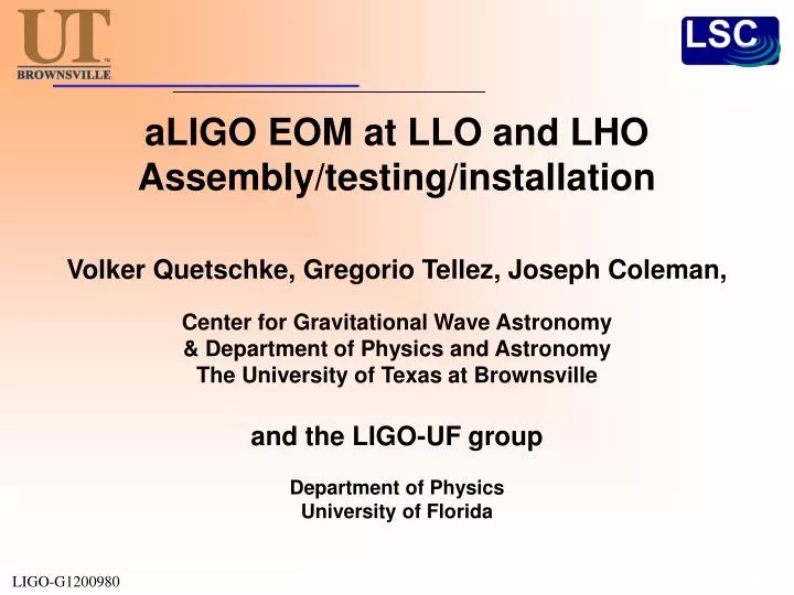
aLIGO EOM at LLO and LHO Assembly/testing/installation. Volker Quetschke , Gregorio Tellez , Joseph Coleman, Center for Gravitational Wave Astronomy & Department of Physics and Astronomy The University of Texas at Brownsville and the LIGO-UF group Department of Physics

E N D
aLIGO EOM at LLO and LHOAssembly/testing/installation Volker Quetschke, Gregorio Tellez, Joseph Coleman, Center for Gravitational Wave Astronomy & Department of Physics and Astronomy The University of Texas at Brownsville and the LIGO-UF group Department of Physics University of Florida LIGO-G1200980
Assembly/testing/installation of the aLIGO phase modulators aLIGO modulators follow the design of the eLIGO modulators, but were adjusted to follow aLIGO specifications: • Three electrode, wedged RTP crystal(rubidium titanyl phosphate - RbTiOPO4) • Wedged avoids cavity effects and reducesamplitude modulation • RTP has low absorption, is capable to handle200W exhibits a small thermal lens • Three electrodes on one crystal minimize the number of optical surfaces (and the price) 15 mm 7 mm 15 mm LIGO-G1200980
Assembly/tuning at UTB • Assemble modulators in clean environment • Build and tune three simultaneous pi-network resonant circuits with 50 Ω input impedance.(9.1 / 24.1 / 45.5 MHz) LIGO-G1200980
Test at UF • Finalize tuning at UF • Measure sidebands • Test high power compatibility Sidebands measured with three 24 dBm signals simultaneouslydriving all threeelectrodes Setup with 150W laser and realistic beam parameters to verify high-power compatibility LIGO-G1200980
Installation at LHO H2 12/2011 Was installed, but shortly after uninstalled and retuned for H1 frequencies LIGO-G1200980
Installation at LLO 07/2011 • L1 modulator install LIGO-G1200980
Modulation depth for 24 dBm drive • Some re-tuning wasdone 04/2012https://alog.ligo-la.caltech.edu/aLOG/index.php?callRep=3027 LIGO-G1200980
RFAM vs. PM RFAM measurements with 24dBm drive https://alog.ligo-la.caltech.edu/aLOG/index.php?callRep=3034 LIGO-G1200980
Installation at LHO 08/2012 Modulation depth for 24 dBm drive • https://alog.ligo-wa.caltech.edu/aLOG/index.php?callRep=3693 LIGO-G1200980
RFAM vs. PM All went well https://alog.ligo-wa.caltech.edu/aLOG/index.php?callRep=3695 LIGO-G1200980
What’s Next? Re-tuning for LIGO India? LIGO-G1200980
Modulation depth / RFAM LLO LLO - Chris explanation:< https://alog.ligo-la.caltech.edu/aLOG/index.php?callRep=2901 > PM vs freq:< https://alog.ligo-la.caltech.edu/aLOG/index.php?callRep=3027 > AM at peak:< https://alog.ligo-la.caltech.edu/aLOG/index.php?callRep=3034 > LHO - PM vs freq:< https://alog.ligo-wa.caltech.edu/aLOG/index.php?callRep=3693 > AM at peak:< https://alog.ligo-wa.caltech.edu/aLOG/index.php?callRep=3695 > LIGO-G1200980