Download
1 / 14
140 likes | 661 Views
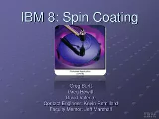
IBM 8: Spin Coating. Greg Burtt Greg Hewitt David Valente Contact Engineer: Kevin Remillard Faculty Mentor: Jeff Marshall. Original Cleaning Disk. Bowl Set. Final Design Overview. Solution 1: Modify the Cleaning Disk

E N D
IBM 8: Spin Coating Greg Burtt Greg Hewitt David Valente Contact Engineer: Kevin Remillard Faculty Mentor: Jeff Marshall
Final Design Overview • Solution 1: Modify the Cleaning Disk • It has been determined through mathematical analysis and a physical inspection that the current cleaning disk has design flaws • These include but may not be limited to the following: • Collection area for solvent is wide and flat, it appears that a significant portion does not flow through the disk • A large majority of solvent sprays only horizontally, causing the bowl set to collect resist above and below this level • The exit area for solvent is too small, an appreciable amount of solvent appears to overflow out of the cleaning disk • Solution 2: Coat the Bowl Set • If the bowl set were to have a coating that defied the buildup of resist, or was readily expurgated, it would aid the cleaning process and compliment Solution 1
Explanation of the Solutions • Solution 1 • A preliminary prototype cleaning disk has been decided upon through the use of a Pugh chart • This prototype increases solvent flow to the entire bowl set • Above the horizontal, at the horizontal, below the horizontal, and the bottom bowl, around the knife edge • The solvent exit velocity (and therefore mass flow rate) has been increased through the use of parabolic channels that will increase the height of fluid in the spinning disk • A radius at the point of impact of the solvent on the disk will cause more solvent to be collected and less to splash back off, a smaller opening will also be employed to catch as much spray as possible • Solution 2 • The company makes a coating called tt-Kote specifically designed for this application, we plan to apply it to a second set of bowls.
Testing and Refining the Solutions:Part 1 • A test stand will be built to replicate the equipment used at IBM • This will consist, in part, of an acrylic glass case • Inside the case there will be a motor to spin the cleaning disk, and to spin a wafer when performing tests to better determine where resist builds up on the bowls • There will be gravity fed nozzles to spray the solvent into the cleaning disk from the back side • A set of bowls will also be contained within, but will be removable • A blower will be connected to the bowl sets to create the correct airflow
Testing and Refining the Solutions:Part 2 • After creation of the test stand, a number of tests will be performed • The current cleaning disk will be tested to compare with the calculations, as a check of their accuracy • Simulated photoresist (magenta inkjet printer ink) will be applied to the bowl sets, both coated and uncoated, using a spinning plastic disk in place of a silicon wafer • This allows for an appropriate characterization of where resist builds up • The prototype cleaning disk design will then be modified based on the results and an actual prototype will be manufactured for testing
Testing and Refining the Solutions:Part 3 • Both cleaning disks will be tested in both sets of bowls to determine two things • If the prototype performs as expected, or what needs to be modified • If the coated bowl outperforms the uncoated bowl • Determine if the performance increase outweighs the cost of the coating • Refine the prototype design and repeat
Manufacture Prototype 02/22 Receive Parts 01/14 Assemble Test Stand 01/21 Test Current Cleaning Disk 02/04 Refine Prototype Design 02/08 Pert Chart Results 04/30 Ship Bowl for Coating 01/21 Bowl/Disk Testing 03/07 Receive Coated Bowl set 04/01 Coated Bowl/Disk Testing Manufacture Final Prototype 04/01 Final Testing 04/09 Return On Investment 12/21 This can be postponed if necessary ———Critical Path - - - - - Non-Crucial Path: Can be postponed if coated bowl set arrives late
Charter • By April 30th, 2008 a final cleaning disk prototype, cleaning recipe, and bowl coating decision will be made that will reduce the frequency with which the bowls are removed for cleaning. Initial testing will be performed to observe cleaning solvent behavior and collect empirical data on the performance of the current cleaning disk, and compare performance of the current bowl with a bowl coated with Nx-Edge tt-Kote. After initial testing, the disk design will be refined and a prototype will be manufactured and tested in both the coated and uncoated bowlsets. Modifications and testing will continue to be performed on the prototype disk until a satisfactory final design is engineered. The results of the testing, the final cleaning disk design, cleaning recipe, and bowl coating decision will be submitted to IBM.