Download
1 / 43
580 likes | 952 Views
Conveyor-Dryer Handling Machine Prepared by : Saad Sami Halaweh Omar Husni Odeh Omar Taher Tuffaha Yahya Hisham Abu- Bieh. An-Najah National University Faculty of Engineering. Supervised by: Dr. Osayd Abdel Fattah. Outline:. What is it all about ? Conveyor design Frame Design

E N D
Conveyor-Dryer Handling Machine Prepared by :Saad Sami HalawehOmar Husni OdehOmar Taher TuffahaYahya HishamAbu-Bieh • An-Najah National University • Faculty of Engineering Supervised by: Dr. Osayd Abdel Fattah
Outline: • What is it all about ? • Conveyor design Frame Design Bolts Design Welding Design Torque Calculations Bearing Design and Selection Motor Selection Sprockets Design and Selection Chain Selection • Drying System Design dryer cover Heat exchanger Fan Selection • Drying experiments
What is it all about ?- Problem definition- Why to use such a machine ?- How does it contribute to the company ?
Conveyor design 1- Frame Design for the leg we assumed b=h ,but in horizontal beams h=1.5*b and yield strength(Sy)=180Mpa, Modules of Elasticity (E) =207Gpa and the safety factor (n) is1.8
The equations that help us in design the frame: summary for forces analysis
this results for identical four legs which L=b=h=40mm Cross section this results for identical four beams which b=40mm, h=60
2- Bolts Design Some eqn. may help us Km = E *d * A *exp(B*d/l) Fm = (1-C)*F –Fi Kb = Ϭservise = Ϭi + Recommendations and needed Nl = N = sp/Ϭ M 5 *0.8 class 9.8 C = At = 14.2 mm2 Ϭi = Fb = Fi +CF
3- Welding Design N=1.5 Sy=100Mpa Ϭ” = Ϭ”’ = That gives us the area which equals 6.74*10-4 m2 And the inertia is 2.666*10-5 m3 So the thickness of weld is 6mm Ϭ’ = Ϭ= Ϭ’ + Ϭ” + Ϭ”’ N=Sy/Ϭ
4- Torque Calculations - This machine is considered as light-weight belt conveyor.- One of the most common formulas to calculate the torque forheavy-weight belt conveyors : - Alternatively, the torque wascalculated By using the following procedure :
- It was found that the added mass required to drive the system equals 45 kg (441 N) – inserted to the pulley which has a diameter of 12 cm.- So the torque induced on the drive shaft is : T = Force*distance = (P) (Pulley diameter / 2) = 441 * 0.06 =26.46 N.m- The force is moved to act on the sprocket which has a diameter of 14 cm.26.46 = T * 0.075 T = 353 NWhere T is the radial force on the drive sprocket – 14 cm in diameter.
5- BearingDesign and Selection Xo = 0.02() = 4.439b = 1.483 = 1.3 (Machinery with light impact)
From angular contact select the bearingwhich has the following dimensions:- UCF201- Bore = 10 mm- Outer diameter (OD) = 30 mm- Width (A1) = 11 mm.- Fillet radius = 0.6 mm.- Shoulder diameters N = 11.5 mm, S = 11.5 mm- C10 = 4.94 KN.- Co = 2.12 KN.
6- Motor Selection Why not to use3-phase synchronous motor ? The required Power transmission by the motor equals 2 * 133 = 266 watt(For two identical conveyors) Three-phase Squirrel-cage Induction Motor Rated torque = 0.5 N.m Rated speed=1473 rpm Rated power= 300 watt= 0.40Hp Efficiency = 0.8 Three-phase Squirrel-cage Induction Motor torque = 102 N.m speed=28 rpm Rated power= 300 watt= 0.40Hp Efficiency = 0.8 Built-inSpeed reducer
7- Sprockets Design and Selection - Two Identical Belt Conveyors - The torque required to drive the system without “ belt slipping “ is : 26.5 N.m - Motor Parameters :Induced Torque = 102 N.mRated Speed = 28 rpm - The motor - sprockets - chain system acts as a speed reducer.
8- Chain Selection The total horse power needed to drive the conveyor is 266 watt We chose chain number 40 P=0.5 in Max power can withstand is 0.37Hp=276 watt
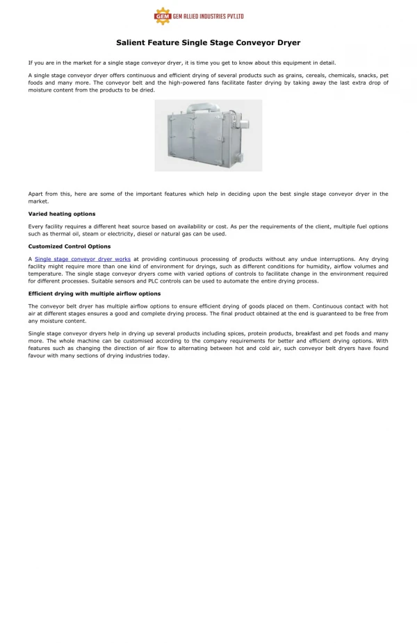
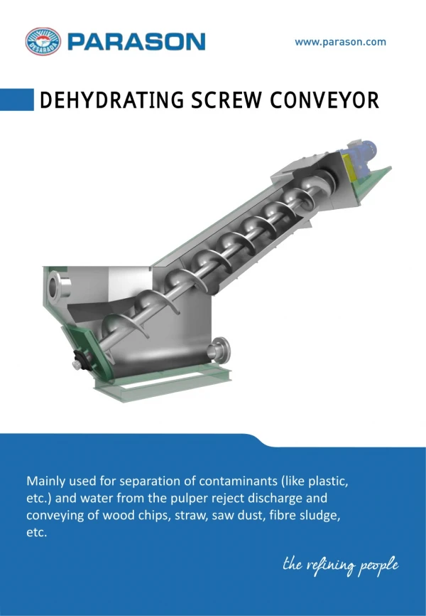
Drying System: 10- Drying System Design What is drying? Drying means removal of relatively small amounts of solvent from solid materials. What is our task? Our task is to design a process to remove solvent from adhesive material taking into account the above constrains to minimize the time of drying as short as possible.
Drying time depends on • the temperature of drying air • air flow rate (amount of air) • drying surface area • Humidity of drying air (solvent content)
Investigations of drying rate parameters • Experimentally, It was found that the optimal parameters of drying rate after carrying out few experiments : • Air temperature is 70C • Drying air flow rate is 90-100 L/min • Amount of adhesive to dry : as the same used on tin plate in the factory (about 5g/tin) The drying time of the adhesive sample (50-52s).
Dryer with pipe manifold air distribution : Previously Heated air in heat exchanger is distributed ensuring enough drying capacity to solvent on adhesive material
Cover of dryer parameters: • X=2.5mm k=54 for carbon steel • X=10mm k=0.045 for Rockwool • Q Losses)cover)= 318.18 W • Q Losses (conveyer) = 150 W • Q (overall)=468.18*3=1404 W Factor =3
Heat exchanger : • Length of tube ()=4.2 m • Q initial=4000 watt • Q for keeping the temperature constant =3000watt
Ventilator (Fan Selection): Type : Centrifugal Fan Power Supply : Electric Model NO. : DF Series Power:0.5kw Type of drive :AC single speed
Its flow rate is determined by rotameter (20-180) l/min. The air is heated through copper coil fitted in hot water. The heating rate is controlled by controllable hot plate. The hot air temperature is measured by digital industrial thermometer (-199-+199) T = 50 c The drying steps: •Switch on the power of air compressor •Heating the water bath that contain the copper coil and heating the air flow, see the •Portioning the proper amount of adhesive on the bottom metal sheet •Drying the adhesive by hot air measuring the time of drying and air temperature. •Drying means that the adhesive material does not stick your finger if you touch it. •The experiment is repeated many times fixing the drying temperature and changing the air flow rate. This results different drying times.
Experimental design : we have conducted many experiments to obtain an equation relates air flow rate, temperature and time
- According to this equation, we have determined the fundamental specifications of the overall system such as the length and the width of the conveyor, heat exchanger design, the required speed to drive the conveyor . relationship between air flow rate and time Q =961.3*t -0.568 Q: air flow rate t : time
Total cost • Motor • Q=266 watt • Cost per hour =0.7 NIS • Operating time=8 hr • Running Cost per day=0.266*8*0.7=1.5 NIS
Heat exchanger • Q Initial =4000 watt • Q for keep heat constant =3000 watt • Operating time=8 hr • Running Cost per day (initial)=4*0.7*1=2.8 NIS • Running Cost per day(keep heat constant )=3*0.7*8=16.8 NIS • Running Cost per day )Heat exchanger)=2.8+16.8=19.6NIS
Ventilator • Q=0.5 Kw • Operating time=8 hr • Running Cost per day=8*0.5*0.7=2.8 NIS • Total cost=2.8+19.6+1.5=23.7 NIS
Conclusion We can conclude : 1- Conveyor-Dryer handling machine contributes to the mitigating of the workforce and reducing the monthly costs.2- No more time-consuming activities in the drying of the coated plates.3- The efficiency of the tin production line is greatly increased.