Download
1 / 87
950 likes | 1.42k Views
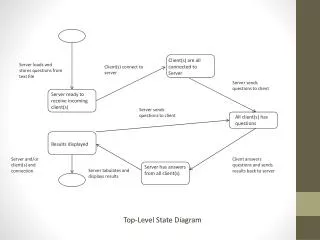
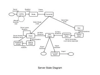
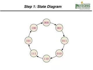
Step 1: State Diagram. Step 2: Next State Table. Step 3 Flip-Flop Transition Table. Step 4: Karnaugh Maps. Step 5 and Step 6 Logic Expressions and Counter Implementation. CLK Q 0 Q 1 Q 2. Counter Decoding. Counter Applications Digital Clock. Logic Symbols.

E N D
Step 5 and Step 6 Logic Expressions and Counter Implementation CLK Q0 Q1 Q2
2-bit Asynchronous Binary Counter Using VHDL The clock will be input C. FF0 the first Flip-flop FF1 the second flip-flop
2-bit Asynchronous Binary Counter Using VHDL entity TwoBitCounter is port(clock: in std_logic; Qa, Qb: buffer std_logic); end entity TwoBitCounter; architecture CounterBehavior of TwoBitCounter is component JKFlipFlop is port( J, K, Clock: in std_logic; Q, Qnot: inout std_logic); end component JKFlipFlop;
2-bit Asynchronous Binary Counter Using VHDL signal I: std_logic; begin I <= ‘1’; FF0:JKFlipFlop port map (J=>I, K=>I, Clock =>clock, Qnot=>Qnot, Q=>Qa); FF1:JKFlipFlop port map (J=>I, K=>I, Clock=>Qnot, Q=>Qb); end architecture CounterBehavior;
Asynchronous Truncated Counters To truncate a counter a clear function must be added to the J-K flip-flop component JKFlipFlopClear is port( J, K, Clock, Clr: in std_logic; Q, Qnot: inout std_logic); end component JKFlipFlopClear
Asynchronous Truncated Counters Example 9-11 Asynchronous MOD6 (0,1,..5) JK flip-flop with clear library ieee; use ieee.std_logic_1164.all; entity ModSixCounter is port(clock: in std_logic; Clr: in std_logic; Q0, Q1, Q2: buffer std_logic); end entity ModSixCounter;
Asynchronous Truncated Counters Example 9-11 architecture CounterBehavior of ModSixCounter is signal Clear: std_logic; component JKFlipFlopClear is port (J, K, Clr, Clock: in std_logic; Q, Qnot: inout std_logic); end component JKFlipFlopClear; signal I: std_logic; begin I <= ‘1’; Clear <= not (Q1 and Q2); FF0: JKFlipFlopClear port map (J=>I, K=>I, Clr=>Clear, Clock =>clock, Q=>Q0); FF1: JKFlipFlopClear port map (J=>I, K=>I, Clr=>Clear, Clock=>Q0, Q=>Q1); FF2: JKFlipFlopClear port map (J=>I, K=>I, Clr=>Clear, Clock=>Q1, Q=>Q2); end architecture CounterBehavior;
Synchronous Counters in VHDL • Synchronous refers to events that occur simultaneously • For synchronous counters all flip-flops are clocked at the same time using the same clock pulse • An example in VHDL would be to use the J-K flip-flop defined as a component then have it clocked using the same clock pulse Figure 9-13
Synchronous Counters in VHDL entity FourBitSyncCounter is port( I, clock: in std_logic; Q0, Q1, Q2, Q3: buffer std_logic); end entity FourBitSyncCounter architecture CounterBehavior of FourBitSyncCounter is signal S0, S1, S2: std_logic; component JKFlipFlop is port(J, K, Clock: in std_logic;Q, Qnot inout std_logic); end component JKFlipFlop
Synchronous Counters in VHDL begin FF0: JKFlipFlop port map (J=>I, K=>I, Clock=>clock, Q=>Q0); S0<= Q0; FF1: JKFlipFlop port map (J=>S0, K=>S0, Clock=>clock, Q=>Q1); S1 <= Q0 and Q1; FF2: JKFlipFlop port map (J=>S1, K=>S1, Clock=>clock, Q=>Q2); S2 <= Q0 and Q1 and Q2; FF3: JKFlipFlop port map (J=>S2, K=>S2, Clock=>clock, Q=>Q3); end architecture CounterBehavior
3-Bit Gray Code CounterExample 9-13 library ieee; use ieee.std_logic_1164.all; entity StateCounter is port(clock: in std_logic; Q: buffer std_logic_vector(0 to 2) ); end entity StateCounter;
3-Bit Gray Code CounterExample 9-13 architecture CounterBehavior of StateCounter is begin process (Clock) begin if Clock = ‘1’ and Clock’ event then case Q is when “000” => Q <= “010”; when “010” => Q <= “110”; when “110” => Q <= “100”; when “100” => Q <= “101”; when “101” => Q <= “001”; when “001” => Q <= “000”; when others => Q <= “000”; end case; end if; end process; end architecture CounterBehavior;
Shift Registers Chapter 10
Basic Shift Register Functions • Data Storage • Data Movement • D flip-flops are use to store and move data
Serial in/Serial out Shift Registers CLK Serial in Serial Out
Serial in/Parallel out shift registers After 4 clock pulses, 0110
Timing Diagram for 8-bit Serial in/Parallel Out CLR’ Data In QA QB QC QD QE QF QG QH CLK
Timing Diagram for 8-bit Parallel Load Shift Resister Loaded 10101010 Output 10101010 Shift/Load’ Output D0 D1 D2 D3 D4 D5 D6 D7 CLK
Bidirectional Shift Registers • Data can be shifted left • Data can be shifted right • A parallel load maybe possible • 74HC194 is an bidirectional universal shift register
74194 data table _____ | MODE | | SERIAL | PARALLEL | OUTPUTS CLEAR | S1 S0 | CLK | LEFT RIGHT | A B C D | QA QB QC QD -----------|----------|--------|--------------------|-----------------------|------------------ 0 | X X | X | X X | X X X X | 0 0 0 0 1 | X X | 0 | X X | X X X X | QA0 QB0 QC0 QD0 1 | 1 1 | POS | X X | a b c d | a b c d 1 | 0 1 | POS | X 1 | X X X X | 1 QAn QBn QCn 1 | 0 1 | POS | X 0 | X X X X | 0 QAn QBn QCn 1 | 1 0 | POS | 1 X | X X X X | QBn QCn QDn 1 1 | 1 0 | POS | 0 X | X X X X | QBn QCn QDn 0 1 | 0 0 | X | X X | X X X X | QA0 QB0 QC0 QD0
74194 parallel load CLR’ S1 S0 QA QB QC QD SR SL A B C D CLK
74194 shift right CLR’ S1 S0 QA QB QC QD SR SL A B C D CLK
74194 shift left CLR’ S1 S0 QA QB QC QD SR SL A B C D CLK
Johnson Counter CLK Q0 Q1 Q2 Q3
Ring Counter CLK Q0 Q1 Q2 Q3
VHDL Code for a Positive-edge Triggered D Flip-flop D flip-flop that will be used as a component. library ieee; use ieee.std_logic_1164.all; entity DFlipFlop is port( D, clock: in std_logic; Q, Qnot: inout std_logic); end entity DFlipFlop;
VHDL Code for a Positive-edge Triggered D Flip-flop continued architecture FlipFlopBehavior of DFlipFlop is begin process(D, Clock) is begin wait until rising_edge (clock); if D = ‘1’ then Q <=‘1’ else Q <=‘0’ end if; end process; Qnot <= not Q; end architecture FlipFlopBehavior;