Download
1 / 21
210 likes | 339 Views
WFC3 Post-Observations Ground System Design. M. Giavalisco H. Bushouse W.King. Introduction. Purpose : Obtain and manipulate all WFC3 SI data from observations through final storage and dissemination to the observer Process data through steps of : Generic conversion (OPUS)

E N D
WFC3 Post-Observations Ground System Design M. Giavalisco H. Bushouse W.King WFC3 IPT PDR
Introduction • Purpose : Obtain and manipulate all WFC3 SI data from observations through final storage and dissemination to the observer Process data through steps of : • Generic conversion (OPUS) • Data reduction and Calibration (CALWF3) • Associations (CALWF3) • Archiving (DADS) WFC3 PDR
WFC3 Layout WFC3 PDR
UVIS Channel 2 2k x 4k EEV Marconi CCDs 200 – 1000 nm High QE 15 micron pixel 0.04 arcsec/pix FOV 160 x 160 arcsec IR Channel 1k x 1k HgCdTe array 850 1700 nm High QE 18 micron pixel Scale 0.13 arcsec/pix FOV 123 x 139 arcsec WFC3 Detectors WFC3 PDR
WFC3 and Other HST S.I. WFC3 PDR
WFC3 Limiting Flux WFC3 PDR
WFC3 Pipeline Routine Science Data Processing Ref files Cal files Engineering MISSION SCHEDULE headers Associations CALWFC3 SOFTWARE Archive • Assembles data from WFC3 into scientifically useful data sets. • Processes the science data using standard calibration tools and reference files. • Calculates error arrays. • Stores raw data sets in the Archive. • Offline Tools/files for Observers to re-calibrate. WFC3 PDR
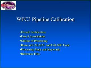
Design Guiding Principles • Maximize Reuse of ACS and NICMOS Pipelines • Treat UVIS and IR channels as similarly as possible • Leverage on the experience from and solutions adopted for WFPC2, NICMOS, STIS, ACS • Incorporate DRIZZLING to enhance effective spatial resolution, remove geometric distortions WFC3 PDR
CALWFC3 Structure • Use ACS structure for pipeline backbone: CALWF3 built from ACSCCD, ACS2D, ACSREJ. • Replace MAMA branch with CALNICA for IR channel. • Implement (minor) modifications and upgrades when required by lack of specific capabilities of ACS’s pipeline. WFC3 PDR
Major Pipeline Building Steps • 1) Required changes for reuse of ACS/NICMOS pipelines: • 1.1) Flatfield implementation (due to geometric distorsions) • 1.2) IR subarrays (UVIS is a copy of ACS WFC) • 1.3) IR overscan pixels (UVIS overscan pixels - built into ACS pipeline) • 1.4) Binning (currently removed from ACS pipeline, but straightforward to replace) • 1.5) Associations - use ACS as baseline • 1.6) WFC3 Keywords (based on ACS and NICMOS) • 1.7) Adopt future NICMOS and ACS science upgrades, as applicable WFC3 PDR
1.1 Flatfield Implementation • Build capabilities in the SW to handle different type of flat fields (pix-to-pix, delta-flat, low-frequency, etc.), as needed for WFC3 • Account for the effect of geometric distortions during flat fielding operation (due to variations in pixel area) WFC3 PDR
1.2 Subarrays • Must use IR subarrays for photometric calibrations of NICMOS standards • UVIS subarrays to follow ACS model : center, size variable in parallel direction • IR subarrays to be of size 512,256,128,64,32 on a side, centered on middle of array • Enable the NICMOS SW to handle OVERSCAN pixels • Must be able to correct for geometric distortions for different size/position subarrays • Must handle relevant calibrations for specific size/position subarrays WFC3 PDR
1.3 Overscan Pixels • Both physical (to remove bias effects) and virtual (to remove amplifier effects) overscan for UVIS - use ACS solutions • Physical overscan (“reference”) pixels only for IR • Used to remove itinerant baselines, biases varying by quadrant, amplifier • Necessary to avoid corruption of edge pixels if binned; DQI flag to be set to acknowledge this (no problem if binning is 1x,2x,3x, and OVSC size is multiple of these numbers) WFC3 PDR
1.4 Binning • Needs to be put back into ACS pipeline • Implemented via binned reference files • Will support 2x2, 3x3 for UVIS • Prevent mixing of overscan and “good” edge pixels => set DQI flag WFC3 PDR
1.5 Associations • Inputs will follow ACS example: science imsets from CALWF3, pixel shift from jitter file/guide star system, “pixel fraction”, pixel weight (bad mask) file • The implementation of DRIZZLING will associate dithered images, no mosaics • DRIZZLING can also do 2 UVIS imsets => 1 UVIS image, geometric distortion corrections as well WFC3 PDR
1.6 WFC3 Keywords • Reuse ACS, NICMOS keyword sets • Keep separate set of keywords for UVIS, IR channels • Resolve contradictions in definitions using ACS conventions • Keep only critical engineering snapshot keywords (about NICMOS) in science headers, remainder in .SPT headers for monthly trending of other engineering keywords WFC3 PDR
1.7 NICMOS Science Upgrades • The pipeline will incorporate the improved CR rejection algorithms (proper treatment of correlated errors) • The upgrades Wwll be meshed with improvements in WFC3 MUX, detector design to track systematics WFC3 PDR
Major Pipeline Building Steps • 2) Desired changes for improved CALWF3 pipeline • 2.1) Specific dithering strategies for DRIZZLING implementation -> dither patterns • 2.2) Geometric distortions corrections: e.g. DRIZZLING, but other options possible- (will monitor ACS solutions/progress) • 2.3) Adopt optimized CR rejection strategies, either with CR-REJECT or during DRIZZLING (will monitor ACS solutions/progress) WFC3 PDR
2.2 DRIZZLING & Dithering Strategies • DRIZZLING will improve angular resolution (but make error analysis more complicated) • Allow either standard TRANS line, box/spiral patterns, or custom ones • DRIZZLING can also paste together two halves of UVIS image WFC3 PDR
2.3 Geometric Distortions • Expected geometric distortion (~10% across the WFC3 FOV) • Need to correct for registration and calibration, and when taking calibrations for the different modes of the instrument. • Need to account for geometric distorsion effects to properly flat-field point vs. extended sources • Correction done in CALWF3 using DRIZZLING • Cubic polynomial description in X,Y w/ cross-terms • Coefficients kept in IDC, SIAF files WFC3 PDR
Conclusions WFC3 Pipeline Will : • Take raw instrument science data and convert it into FITS files suitable for science analysis • It will support WFC3 Thermal Vacuum ground testing and verification at NASA/GSFC • Take advantage of maximal reuse of ACS and NICMOS pipelines. • It will build on ACS pipeline structure with CALNICA replacing the MAMA code, including DRIZZLING WFC3 PDR