Download
1 / 37
380 likes | 818 Views
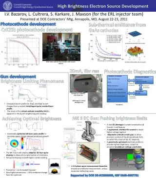
High Average Brightness Electron Beam Production at Cornell University. 9/13/2013 Jared Maxson (for the Cornell ERL Team ) PSTP 2013. Outline. The Cornell ERL injector prototype Milestones in commissioning: World Record average current Measurement of low emittance

E N D
High Average Brightness Electron Beam Production at Cornell University 9/13/2013 Jared Maxson (for the Cornell ERL Team) PSTP 2013
Outline • The Cornell ERL injector prototype • Milestones in commissioning: • World Record average current • Measurement of low emittance • New Gun and Diagnostic Beamline • Redefining the “ultimate gun” (in brightness terms) • New Gun design features • Processing results, ongoing rebuild • Beamline experiments
What we want: CESR Linac 1 Injector Linac 2 Sync. Beamlines • Beam parameters: 5GeV, 100mA CW current with energy recovery: • Energy of spent bunch captured entering linac again 180 degrees out of phase.
What we’ve got so far: CESR Injector
How are we doing? • These are the major milestones I’ll be focusing on. • Many things applicable to polarized sources I can’t cover in the time allotted, please interrupt me with questions if something interests you. • Is a 750kV gun actually required? We don’t think so.
World record photoinjectorcurrent! • Dunham et. al. APL 102, 034105 (2013) • Using GaAs: off center active area Before use After use • Visible damage due to ion back bombardment at EC. • Overall speckling from heat cleaning. • Each vacuum trip (coupler) corresponds to a damage spot 1 to 1. Running parameters: Beam energy: 5 MeV Beam loss: ~2e-8 (1 nA, based on radiation measurements)
World record photoinjectorcurrent! • Dunham et. al. APL 102, 034105 (2013) • Using multialkalioff center, a robust bulk emitter: CsK2Sb CsK2Sb Before use After use • 60mA run with CsK2Sb had ~30 h 1/e lifetime • Pgun=1.13x10⁻¹¹ torr 3.0x10⁻¹¹ torr • Likely due to beam scraping • 65mA run with NaKSbhad ~66 h 1/e lifetime NaKSb
Current Stability Shaping iris ~30 m long Clipped beam! Transport line Thermal lensing • Beam Clipping from thermal lensing+shaping iris can yield fast beam current fluctuations • Con operate under these conditions successfully, but not ideal. • Solution: use a Pockelscell as a fast feedback shutter to adjust laser intensity to compensate for intensity fluctuation. Hence: Controlled by feedback Scaled laser power 4 hours
Measurement of Low Emittance • ERL injector equipped with full 6D phase space measurement system: • 30 μm slit pairs + fast scanner magnets + deflector cavity+ 15 deg. dipole spectrometer • Measured in the merger section
GPT Modeling + Alignment • Simulate using General particle Tracer. Take no shortcuts! • Field map for each element, • either native 3D, or use custom elements to perform off axis expansion. Solenoid alignment: Beam based transfer matrix approach/ mechanical adjustment iterations (~10 um) Gun centering: Center laser beam using ES focusing 3D time dependent maps including asymmetric coupler effects
Virtual Accelerator Interface • A GUI for GPT written in MATLAB reads each element setting, and updates the simulation value. Full space charge calculation. • Allows for “real time” (minutes) comparison of simulation and expt.
Final Phase space results More info: "Demonstration of Low Emittance in the Cornell Energy Recovery Linac Injector Prototype", PRSTAB 16 (2013) 073401
Final Phase space results Horizontal Vertical
Ultimate Brightness Gun • For decades, conventional wisdom has dictated that the brightest DC gun is the one with the highest voltage. • Is this true in practice? How high is high enough? 500kV? 1MV? Do we need to go to SRF? • Full simulation and optimization can settle the question. • Consider an injector akin to ERL prototype. • Create field maps for both SRF and DC guns, varying many parameters of their geometry, and beamlinesetpoints.
Gun Geometries SRF parameters: Eacc=25 MV/m Epk/Eacc<2 Hpk (mT)/Eacc (MV/m)=4.26 DC parameters: Shortest distance between cathode and anode computed, and voltage constrained to be less than breakdown voltage.
Fields and Laser Dist. DC fields (w/ buncher) SRF fields (w/o buncher) Transverse Laser distribution: assume a Gaussian with variable and cutoff radius. Temporal Laser Distribution
Ultimate Brightness Gun DC SRF Case: 120 meV V=470kV Ecath=5.1 MV/m V=1.6 MV
Lessons Learned • DC and SRF emittances were very close (~20%), though the voltages were 3x different! • We owe this to precise emittance compensation. • The small emittances of simulations can be achieved—ERL photinjector is proof. • In DC case: • Chose balance between moderate voltage (470 kV), but and high photocathode field. Some cases have no cathode focusing! • Ecathdetermines maximum achievable brightness! hv + e- V0
New Gun Overview • Take lessons to heart. Step 1: Want to get to 500kV! Segmented, shielded insulator SF6 @ 4 atm 50’’ 316LN stalk Kaiser 600kV PS 5cm gap, 25deg focusing 100-300 MΩ Ion pump behind 3500l/s Capacitorr NEG pump (x2)
Segmented Insulator • Mitigate punch-through: shield the ceramic! • Brazed Alumina segments with kovar ring in each joint. • Inside: Cu protection rings entirely shield ceramic from field emitted electrons • Outside: Mount 500MΩ resistors between each segment (1GΩ / 2 in parallel) • Allows differentiation between field emission going to ground or going to the rings! • If anode floats, can distinguish between emission from stalk, cathode, and direct to ground.
Movable anode • Cathode field is a crucial figure of merit. • Translatable anode allows us to tailor the field. 2 welded bellows 2-5cm adjustable gap Gate valve Anode electrode
Assembly and Processing • Followed SRF cleaning procedure: Chemistry on all electrodes, HPR all surfaces, and clean room assembly. • During NEG activation, the vacuum window cracked. Large burst of particles from oxygen contamination while hot. • Processing was rocky: • Excess current from power supply (steady state 10s of uA, spikes up to 100uA and beyond), • Excess current on resistors (spikes of ~10uA) • Current on floating anode (<1uA, excess by definition) • Radiation inside lead (up to 10 R/hour) • Vacuum (base 1e-10 torr) spikes of 1e-7…or worse. • Reached 390 kV using gas processing, didn’t translate to vacuum (~350kV). • Decided to open the gun to investigate…
Assembly and Processing • Purged with N2 gas, counted particles 0.3 um and larger. Saw a few bursts of large counts. • Quickly sealed and tried to reprocess without success. Decided to reclean and rebuild. • Began rebuild in SRF cleanroom facility (always class 10). • Stalk showed definite signs of field emission—the rings have thusfar been robust!
Beamline Overview • Small (~3m) beamline with full 6D phase space measurement capability • Want to demonstrate brightness limit by adjusting electric field of the C-A gap • Want to use real-time optimization teqniques to put emittances to the limit • Also want to directly measure the virtual cathode instability • Has only been indirectly measured by Dowell, Phys. Plasmas 1996 Laser in Coll. Slit Def Cav Corr. Mag. Sol EMS Slits F.cup Gun Anode Spec. Dipole https://wiki.lepp.cornell.edu/ERL/Private/R128Beamline
Summary • Cornell photoinjector has nearly demonstrated full feasibility of injecting low emittance, high average current electrons for an ERL light source • High current record: 75 mA using multialkali • Emittances < 0.4 um normalized in merger • Constructing new photogun using input from optimization • Push for both photocathode field +voltage, rather than simply voltage. • New gun currently in rebuilding phase, should be back on in a few months!
Summary Special Thanks to: Ivan Bazarov, Bruce Dunham, Karl Smolenski, Luca Cultrera, ColwynGulliford, and SiddharthKarkare
Full Phase Space Measurement • EMS system measures vertical phase space, via two horizontal 30um slits, and box correctors (4 total). • Deflector cavity converts time position to vertical position-> allows measurement of longitudinal profile (bunch length) • Vertical slits make resolution better. • A collimating slit (120 um vertical slit) and dipole magnet measures energy spread
Full Phase Space Measurement EMS Cor. 2 dE/E Y (mm) EMS Cor. 1 All slits in, deflector on, through dipole, On final viewscreen: Time (ps)
Laser Parameters for Emittance • Have two sets of crystals (5 total) to produce a long pulse: • Can also use subset for shorter pulses. • Careful, careful alignment to reduce spatial distortions.
Online optimization • Do charge scan optimization using GA data and in real time. 3D Laser Sims/GA Solenoid sigma R angles Measure @ multiple charges GA Settings Real Time GA “tweak”
Virtual Cathode Instability virtual cathode instability virtual cathode instability Space charge cancels accelerating force , density oscillation about unstable equilibrium.
Virtual Cathode Instability Dowell et al. 1997 Only measured indirectly!
Virtual Cathode Instability • When will this happen? Bazarov et. al 2009 say if the bunch is “pancake like” , then: • Is this true? • 24 psrms, and , mm • ! • For slightly longer pulses, we have to modify Child-Langmuir law (1D): “Effects of pulse-length and emitter area on virtual cathode formation in electron guns”, Valfells et. al 2002.
Virtual Cathode Instability • There are works that extend the CL law to 3D via scaling from simulations. • “Multidimensional short-pulse space-charge-limited flow”,Koh et al. 2006. • “Two-dimensional electromagnetic Child–Langmuir law of a short-pulse electron flow”S. H. Chenet al., Phys. Plasmas 18, 023105 (2011) • They write • Correction factors can be ~2 for beams with A~1! • No one seems to have measured this. Sims are challenging—need exp’t input! • Question of magnetic field role in VC oscillations? Is GPT even doing it remotely correctly?
Why Transverse position? Z(m) Y (mm)