Major Connectors
610 likes | 2.15k Views
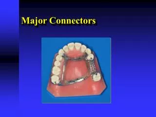
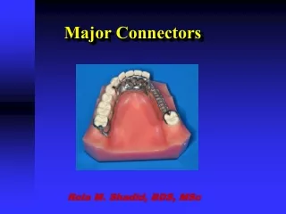
Major Connectors. Rola M. Shadid, BDS, MSc. Major Connector. A major connector is the component of the RPD that connects the parts of the prosthesis located on one side of the arch with those on the opposite side.

Major Connectors
E N D
Presentation Transcript
Major Connectors Rola M. Shadid, BDS, MSc
Major Connector • A major connector is the component of the RPD that connects the parts of the prosthesis located on one side of the arch with those on the opposite side. • It is that unit of the RPD to which all other parts are directly or indirectly attached.
Functions of Major Connector • Unification • Partial denture acts as one unit • Connects various parts
Functions of Major Connector • Stress Distribution • Distributes functional loads to both teeth & mucosa
Functions of Major Connector • Cross-Arch Stabilization * (Counterleverage) • Bracing elements on one side of the arch providing stability to the other
Requirements of Major Connector • Rigidity * • Functions as one unit
To Increase Rigidity • Use a more rigid alloy • Chrome-cobalt > gold alloys; cast > wrought • Shape (cross-section) • 1/2 round > 1/2 pear shaped > flat bars
To Increase Rigidity • Increase the bulk as the length increases • Corrugate linguoplate or rugae areas
Requirements • Non-Interference with soft tissues • Should not enter undercut areas • avoid by changing path of insertion • or by using blockout
Non-Interference With Tissues • Avoid terminating on: • Free gingival margin • Cross abruptly at 90o • Relief is used to minimize impingement
Borders of maxillary connector should be placed a minimum of 6 mm away from and parallel to the gingival margins. Border of mandibular connector should be located a minimum of 4 mm below the gingival margin
Non-Interference With Tissues • Avoid terminating on: • Hard structures such as the mid-palatal suture or mandibular tori • Place relief
Non-Interference With Tissues • Avoid terminating on: • Lingual frenum & the movable soft palate • Soft tissue movements must also be allowed
Minimize Food Impaction • Locate margins away from the FGM • Eliminate "traps" or large concavities where food can collect
Unobtrusive * • Smooth transition from connector to denture base - butt joint
Unobtrusive • Line angles and edges should be smooth and rounded • Borders should not interfere with speech
Relief • Mandibular major connectors should be located and/or relieved to prevent impingement of tissue because the distal extension denture rotates in function. • Except for a palatal torus or prominent median palatal suture area, maxillary connectors ordinarily require no relief.
Mandibular Major Connectors • Lingual Bar • Lingual Plate • Sublingual bar • Lingual bar with cingulum bar (continuous bar) • Labial bar • Swing lock design
Mandibular Major Connectors • Lingual Bar • Most common in mandibe • Use whenever possible
Mandibular Major Connectors • Lingual Bar • Shape • Flat on tissue side • Convex or tear-drop on tongue side • (1/2 pear shape, with thin edge toward teeth)
Lingual Bar • Located above moving tissue but as far below the gingival tissue as possible • The superior border should be tapered toward the gingival tissue superiorly with its greatest bulk at the inferior border, resulting in a contour that is a half-pear shape.
Mandibular Major Connectors • Lingual Bar • Size • Occluso-gingival width = 4 to 6 mm • Thickness = l.5 to 2 mm
Inferior Border of Lingual Bar * • Patient lifts tongue • Activates floor of mouth • Measure from tip of probe to free gingival margin OR • Make impression with lifted tongue • Measure on cast
Lingual Bar • Position • Superior border • 3-4 mm or more below FGM • As far from gingival margin as possible
Mandibular Major Connector Relief • Eliminates impingement • Wax spacer (relief) placed under major connector • One thickness of 30 gauge wax *
Lingual Bar Indication The lingual bar should be used for mandibular RPD where sufficient space exists between the slightly elevated alveolar lingual sulcus and the lingual gingival tissue (more than 8 mm)
Contraindications for Lingual Bar • Remaining natural anterior teeth severely tilted lingually • Interfering lingual tori • High attachment of lingual frenum • Interference with elevation of the floor of the mouth during functional movements (< 8 mm)
Lingual Plate (Linguoplate) • Lingual bar with extension over cingula of anterior teeth • Use where a lingual bar cannot be used
Lingual Plate Inferior border at the ascertained height of the alveolar lingual sulcus when the patient's tongue is slightly elevated.
Lingual Plate • Rest at each end of lingual plate • Prevents forces being directed facially • Easier denture tooth addition than bar *
Lingual Plate Variations • May show through embrasures
Lingual Plate Indications • Potential Impingement from lingual bar • High floor of the mouth (< 8 mm) • Prominent lingual frenum • Lingual tori
Lingual Plate Indications • The residual ridges in Class I arch have undergone such vertical resorptionthat they will offer only minimal resistance to horizontal rotations of the denture through its bases. • For using periodontally weakened teeth to furnish support to prosthesis and to help resist horizontal rotation of the distal extension type of denture. (act as periodontal splint)
Mandibular Lingual Bar with Continuous Bar (Cingulum Bar)(Kennedy Bar, Double Lingual Bar) • Lingual bar with secondary bar on cingula of anterior teeth *
Mandibulat Lingual Bar with Continuous Bar Indications When a linguoplate is otherwise indicated but the axial alignment of anterior teeth is such that excessive blockout of interproximal undercuts would be required. When wide diastema exists between mandibular anterior teeth and a linguoplate would objectionably display metal in a frontal view.
Mandibulat Lingual Bar with Continuous Bar • Potential food trap between two bars • Normally avoid
Maxillary Major Connectors • Anterior-Posterior Palatal Strap • Palatal plate-type connector • Single palatal strap • U-shaped palatal connector (Anterior Palatal Strap) • Single palatal bar • Anterior-posterior palatal bar
Maxillary Major Connectors Whenever it is necessary for the palatal connector to make contact with the teeth for support, definite tooth support by definite rest seats should be provided *
Maxillary Major Connectors • Terminate 6.0 mm or more from free gingival margin when possible
Anterior-Posterior Palatal Strap* • Maximum rigidity • Minimum bulk • Use in most cases • Especially torus palatinus
Anterior-Posterior Palatal Strap Indications • Class I and II arches in which excellent abutment and residual ridge support exists, and direct retention can be made adequate without the need for indirect retention. • Long edentulous spans in Class II, modification 1 arches. • Class IV arches
Anterior-Posterior Palatal Strap Indications • Inoperable palatal tori that do not extend posteriorly to the junction of the hard and soft palates. • The only condition preventing its use is when there is an inoperable maxillary torus that extends posteriorly to the soft palate.
Anterior-Posterior Palatal Bar • A narrow (A-P) variation of anterior-posterior palatal strap • Double palatal bar connector • Requires greater bulk for rigidity
Anterior-Posterior Palatal Bar • More objectionable to the patient • Strap connectors provide greater distribution of stresses
Palatal Plate-Type Connector • Covers one half or more of the hard palate • Maximum tissue support • Connector of choice in long distal extension cases
Palatal Plate-Type Connector • Greater stability and stress distribution • Not used with torus • Increases retention
Palatal Plate-Type Connector • Connector should: • be fabricated of uniformly thin metal * • have accurate anatomic reproduction of the rugae • improves strength and rigidity
Palatal Plate-Type Connector • Connector should: • Cover same area as complete denture posteriorly • Have large surface area of mucosal contact • improves potential for retention
Palatal Plate-Type Connector Forms • A cast plate between two or more edentulous areas • A complete or partial cast plate that extends posteriorly to the junction of the hard and soft palate