Download
1 / 12
120 likes | 273 Views
This document outlines essential modifications to the existing water distribution system, including the integration of new supply and distribution lines. Key features include the connection of a new tank and updated piping layout, addressing elevation changes, flow rates, and head loss calculations in the supply lines. The specifications for trenching and material lists for constructing the pipeline are provided in line with EWB guidelines. These updates are critical for improving water delivery and system efficiency while ensuring compliance with best practices in water resource management.

E N D
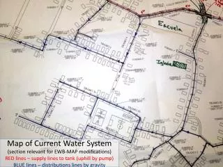
Map of Current Water System (section relevant for EWB-MAP modifications)RED lines – supply lines to tank (uphill by pump)BLUE lines – distributions lines by gravity
Proposed update to Water System (section relevant for EWB-MAP modifications)RED lines – supply lines to tank (uphill by pump)BLUE lines – distributions lines by gravity A F NEW DISTRIBUTION LINE 2a NEW SUPPLY LINE 1 D NEW DISTRIBUTION LINE 2b E NEW DISTRIBUTION LINE 2c B NEW TANK C
Piping System Layout New Pipelines Waypoints • Supply Line 1 to new tank (A-B-C) • Length = 365 m + tank connection (assume + 10 m) = 375 m • 1 bend, 1 tee, 3 elbow, 2 valves, 1 exit • 17 m elevation rise + tank height • Hill rises to 643 m then valley falls t0 640 m on connecting road (D-B) • ~175 gpmflowrate • Distribution line connection 2a from lower Tramo 3b to lower Tramo 6 (E-F) • 105 m length, elevation change unclear, guess 10 m drop • Distribution connection 2b from upper Tramo 3b to upper Tramo 6 (B-D) • 120 m length, 8 meter drop with low point at 640 m (3 m below D) • Distribution line 2c from new tank to new connections (C-B-E) • 255 m length, 11 meter elevation drop
Proposed update to Water System (section relevant for EWB-MAP modifications)RED lines – supply lines to tank (uphill by pump)BLUE lines – distributions lines by gravity A 20 m 240 m NEW SUPPLY LINE 1 B NEW TANK C 105 m
Estimate of head losses in supply pipe 1 (smooth PVC) 4” PVC sufficient to keep major and minor losses to >10% of the elevation change
Supply Pipe 1 Pipe Profile(not to scale) C 651 m 655 m B Elevation: 640 m 643 m 105 m 638 m D A 240 m 640 m 20 m Tee connect to 6” pipe Gate Valve 45° Elbow 90° Elbow Gate Valve 90° Elbow 90° Elbow Pipe Exit PIPE FITTINGS NEW TANK
Supply Pipe 1 Trenching • Based on recommendations from EWB Water Resource Guidelines: • 45 cm trench depth • 10 cm bedding (2-12 mm soil) if stones/rocks present in trench • Back-fill with soil that is free of lumps, from stones (>3 cm), and from organic matter • PVC pipe joined in trench and cure for >10 hr prior to pressurizing. Keep joints exposed to check for leaks • For road crossing, bury PVC pipe inside steel or concrete pipe (ID > diameter of PVC joints) and bury at same depth as standard trench 45 cm trench depth 10 cm bedding
Thrust Anchors for Elbows &Tees From Russ Turner, Tetratech
Thrust Anchor Dimensions • Based on • 4” PVC PIPE • 45 cm Trench Depth • Height of Anchor • 22.5 cm • Length of Anchor Backing against undisturbed material: • 90° BEND: L = 83 cm • 45° BEND: L = 41 cm • Tee: L = 41 cm
Supply Pipe 1 Materials List • 4” PVC pipe (Schedule 40) in 6 m lengths – 62 pieces • 4” PVC 45° Elbow – 1 piece • 4” PVC 90° Elbow – 1 piece • Tee connector & Adapter from 6” PVC main to 4” branch line – 1 piece • PVC primer, PVC cement, applicators, and cleanup • Gate/Ball valves (PVC or steel ?) – 2 pieces • 4” Steel Pipe (5 m) – 1 piece • 4” Steel 90° Elbow – 2 pieces • 4” PVC-Steel Pipe Connector – 1 piece • Bed material for trench (2-12 mm), if necessary • Fill material, if necessary • Concrete for Anchoring Piping at Bends • Concrete/Rebar for Valve boxes and lids • Tools for cutting, de-burring, connecting pipe
EPA-NET Simulation for Supply Line 1 Matches Excel Calculations