Download
1 / 6
60 likes | 451 Views
6/4/2012. 2. 8085A Address Space. Unlike modern microprocessors, the 8085A microprocessor has two address spaces.A 16-bit address space, nominally for memory devicesAn 8-bit address space, nominally for input/output devicesThe two address spaces are distinguished by the processor by the st

E N D
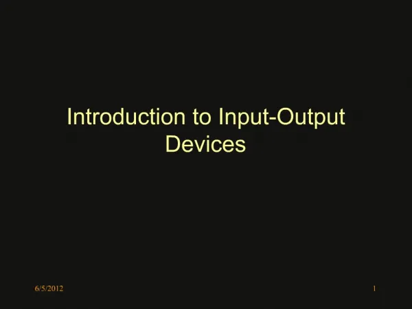
1. 6/5/2012 1 Introduction to Input-Output Devices
2. 6/5/2012 2 8085A Address Space Unlike modern microprocessors, the 8085A microprocessor has two address spaces. A 16-bit address space, nominally for memory devices An 8-bit address space, nominally for input/output devices
The two address spaces are distinguished by the processor by the state of the status line.
3. 6/5/2012 3 Memory and IO Instructions Separate sets of instructions are used to access storage locations in the memory address space of the processor and the IO address space of the processor.
All external data transfer instructions other the IN port and OUT port access addresses in the memory space of the processor. Execution of this class of data transfer instruction forces the status line IO / M* to be logic �0�.
The instruction IN port reads 8-bits of data from the I/O location with the 8-bit address port. Execution of this instruction forces the status line IO / M* to be logic �1�.
The instruction OUT port writes 8-bits of data to the I/O location with the 8-bit address port. Execution of this instruction forces the status line IO / M* to be logic �1�.
4. 6/5/2012 4 A Simple Two-Port, Input Device In its most simplistic form an input port comprises a set of tri-state buffers.
The input to the buffers is connected to the data source. The outputs of the buffers are connected to the processors data bus.
Buffer control is provided by combinational circuitry receiving inputs from the processors control and address busses and from external IO decoding logic.
5. 6/5/2012 5 Control Inputs to IO Port The address input connections to the IO device provide a mechanism to select a particular 8-bit port from the ports within the device.
The RD/ input line specifies when the input tri-state buffers can be enabled onto the data bus.
The CS/ input line enables the processor to select a particular IO device when the computer system has a number of IO devices.
The CS/ line is usually fed from the output of decoding logic which decodes high order address lines.
6. 6/5/2012 6 Example of IO Decoding
7. 6/5/2012 7 A Simple Two-Port, Output Device In its most simplistic form an output port comprises a set of data latches buffers.
The outputs of the latches are connected to the peripheral device. The inputs to the latches are connected to the processors data bus.
Latch control is provided by combinational circuitry receiving inputs from the processors control and address busses and from external IO decoding logic.