Download
1 / 15
180 likes | 526 Views
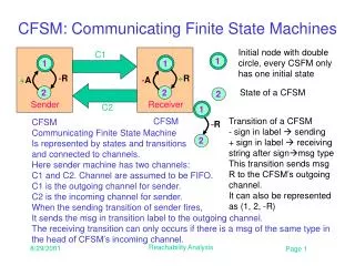
- R. - R. 2. 1. 1. 1. 2. 1. 2. 2. CFSM: Communicating Finite State Machines. Initial node with double circle, every CSFM only has one initial state. C1. + R. + A. - A. State of a CFSM. Sender. Receiver. C2.

E N D
-R -R 2 1 1 1 2 1 2 2 CFSM: Communicating Finite State Machines Initial node with double circle, every CSFM only has one initial state C1 +R +A -A State of a CFSM Sender Receiver C2 Transition of a CFSM- sign in label sending+ sign in label receivingstring after signmsg typeThis transition sends msg R to the CFSM’s outgoing channel.It can also be represented as (1, 2, -R) CFSM CFSMCommunicating Finite State Machine Is represented by states and transitions and connected to channels. Here sender machine has two channels: C1 and C2. Channel are assumed to be FIFO. C1 is the outgoing channel for sender. C2 is the incoming channel for sender. When the sending transition of sender fires, It sends the msg in transition label to the outgoing channel. The receiving transition can only occurs if there is a msg of the same type in the head of CFSM’s incoming channel. Reachability Analysis
C1 C1 -R -R +R +R +A +A -A -A Sender Sender Receiver Receiver C2 C2 1 2 1 2 1 2 1 2 Operation of CFSM current state • When the network starts, the current states of both machines are set at their initial states. • Receiver at state 1 can not fire the outgoing transition (1, 2, +R) • Sender at state 1 can fire the outgoing transition (1, 2, -R), and result in current state of sender changed to 2 and msg R is put in channel C1. R Reachability Analysis
C1 C1 -R -R +R +R +A +A -A -A Sender Sender Receiver Receiver C2 C2 1 2 2 1 1 2 1 2 R Operation of CFSM: Step 2 • Now sender at state 2 has (2,1,+A) as its outgoing transition. There is no msg A in C2, therefore this receiving transition cannot be fired. It waits. • Receiver at state 1 checks its outgoing receiving transition (1,2,+R) and found the msg label matched with the msg in the head of C1. It fires the transition, takes in the msg R (removes from C1) and changes its current state to state 2. Reachability Analysis
C1 C1 -R -R +R +R +A +A -A -A Sender Sender Receiver Receiver C2 C2 1 2 2 1 1 2 1 2 R Operation of CFSM: Step 3 • Now sender at state 2 has (2,1,+A) as its outgoing transition. There is no msg A in C2, therefore this receiving transition cannot be fired. It waits. • Receiver at state 1 checks its outgoing receiving transition (1,2,+R) and found the msg label matched with the msg in the head of C1. It fires the transition, takes in the msg R (removes from C1) and changes its current state to state 2. Reachability Analysis
C1 C1 -R -R +R +R +A +A -A -A Sender Sender Receiver Receiver C2 C2 2 1 2 1 1 2 1 2 Operation of CFSM: Step 4 • Now sender still at state 2 has (2,1,+A) as its outgoing transition. There is no msg A in C2, therefore this receiving transition cannot be fired. It waits. • Receiver at state 2 checks its outgoing sending transition (1,2,-A). It fires the transition, put msg A in C2, and changes its current state to state 2. A Reachability Analysis
C1 C1 -R -R +R +R +A +A -A -A A Sender Sender Receiver Receiver C2 C2 1 2 2 1 2 1 2 1 Operation of CFSM: Step 5 • Receiver at state 1 checks its outgoing sending transition (1,2,+R). There is no msg R in C1. It waits. • Now sender at state 2 has (2,1,+A) as its outgoing transition. There is a msg A in C2, therefore this receiving transition can be fired. It reads in A (remove from C2) and changes state to 1. Now Both machines get back to their initial states. Reachability Analysis
C1 C1 C1 -R -R -R +R +R +R +A +A +A -A -A -A Sender Sender Sender Receiver Receiver Receiver C2 C2 C2 1 1 1 1 1 2 2 1 2 2 2 2 What could happen next? • In CFSM model, we assume only one transition can be fired in a time. No two simultaneous firing. Sender: (1,2,-R) Receiver: (2,1,-A) R A Reachability Analysis
C1 R -B +R +A -A -R -R -R Sender Receiver C2 1 1 1 1 2 2 2 2 2 2 1 1 What could happen next? • Sender cannot move. • Receiver can either receive msg R or send msg B. • How many msgs can be in C1 for this network? How about C2? Receiver: (1,2,-B) Receiver: (1,2,+R) C1 C1 R -B -B +R +R +A -A +A -A B Sender Receiver Sender Receiver C2 C2 Reachability Analysis
-R 2 1 2 1 What could happen next? C1 +R +A -A • Receiving state is a state where all its outgoing transition are all receiving transition. It can not move without msg in its incoming channel. • Both machines are at receiving states and channels are empty. This is called deadlock. The network can not progress further. Sender Receiver C2 Reachability Analysis
C1 +R +A -A -R B Sender Receiver C2 2 1 2 1 Unspecified Reception Error • There is msg B in C2 but sender does not have a receiving transition with msg B. • This is called unspecified reception. The network can not progress further. Reachability Analysis
-R 3 2 1 1 2 Non-executable States and Transitions C1 -C • State 3 of Receiver will never be executed or become the current state. It is called non-executable state. • Transitions (2,3,+B) and (3,1,-C) will never be executed. They are called non-executable transitions. • How does one know they will never be executed? +R +A -A B +B Sender Receiver C2 Reachability Analysis
R B E E E 2 2 1 2 2 E E A E E 2 1 1 1 1 Channel C1’s content Sender’sState 1 2 1 2 Receiver’sState Channel C2’s content Reachability Analysis gs0 A process of generating all possible reachable states from the initial global state -B -R C1 gs1 -B gs2 +R -R +A -A Unspecified Reception Receiver do not know how to receive B E: channel empty +R Sender Receiver C2 gs3 CFSM CFSM gsn Global State ID -A gs4 +A global state/reachable state Reachability Graph Reachability Analysis
Reachability Analysis • Starting from initial global state, where channels are empty and machines at their initial state, explore all possible reachable state by firing the possible transitions (and generating global states) from any given reachable state. • All deadlock and unspecified reception errors will be captured/marked as individual global state. • By examining the number of msgs in the channels we can design the buffer size for the protocol. • Can detect non-executable states and transitions by marking those state are touched and transition that are fired during the reachability analysis. Reachability Analysis
Reachability Analysis Exercise • Perform the reachability analysis on the Network (M, N). • What sizes of buffers are needed for the two FIFO channels? • Are there non-executable states or transitions? Reachability Analysis
Solution • One unspecified reception. • Both channels needbuffer size of 2.(see gs8 and gs9) • No non-executablestates and transitions. • Since both machinessend same typesof msgs. We useMachine: to specifywhich machine firesthe transition. Reachability Analysis