Download
1 / 71
730 likes | 1k Views
An Introduction to CDMA Air Interface: TIA/EIA/IS-95A. Advanced Technology Center Computer & Communications Research Laboratories Industrial Technology Research Institute Ray-Guang Cheng crg@atc.ccl.itri.org.tw. Contents. Introduction Forward CDMA Channel Reverse CDMA Channel.

E N D
An Introduction to CDMA Air Interface: TIA/EIA/IS-95A Advanced Technology Center Computer & Communications Research Laboratories Industrial Technology Research Institute Ray-Guang Cheng crg@atc.ccl.itri.org.tw
Contents • Introduction • Forward CDMA Channel • Reverse CDMA Channel
Multiple Access • FDMA • Advanced Mobile Phone Service (AMPS) and Total Access Communications System (TACS) • AMPS systems use 30 kHz "slices" of spectrum for each channel • Narrowband AMPS (NAMPS) requires only 10 kHz per channel • TACS channels are 25 kHz wide • TDMA • IS-54 systems, designed to coexist with AMPS systems, divide 30 kHz of spectrum into three channels • PDC divides 25 kHz slices of spectrum into three channels • GSM systems create 8 time-division channels in 200 kHz wide carriers
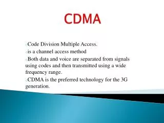
Multiple Access • CDMA • unique digital codes are used to differentiate subscribers • codes are shared by both MS and BS • all users share the same range of radio spectrum • Benefits of CDMA: • Capacity increases: 8 to 10 times (AMPS); 4 to 5 times (GSM) • Improved call quality • Simplified system planning • Enhanced privacy • Improved coverage characteristics • Increased talk time for portables • Bandwidth on demand
CDMA • There are two CDMA common air interface standards: • Cellular (824-894 MHz) - TIA/EIA/IS-95A • PCS (1850-1990 MHz) - ANSI J-STD-008 They are very similar in their features, with exceptions of the frequency plan, mobile identities, and related message fields. • IS-95A • 45 MHz spacing for forward & reverse channel • Permissible frequency assignments are on 30 kHz increments • W/R = 10 log (1.2288 MHz/9600Hz) = 21 dB for the 9600 bps rate set • ANSI J-STD-008 • 80 MHz spacing for forward & reverse channel • Permissible frequency assignments are on 50 kHz increments
Forward CDMA Channel of IS-95A • From BSS to MS • It carries traffic, a pilot signal, and overhead information. • Pilot is a spread but unmodulated DSSS signal. • Pilot and overhead channels establish the system timing and station identity. • Pilot channel is also used in the mobile-assisted handoff (MAHO) process as a signal strength reference. • FEC code rate is 1/2 and the PN rate is 1.2288 MHz (1.2288 MHz = 128*9600 bps).
Forward Link Channel Parameters Channel Sync Paging Traffic Data rate 1200 4800 9600 1200 2400 4800 9600 bps Code repetition 2 2 1 8 4 2 1 Modulation symbol rate 4800 19,200 19,200 19,200 19,200 19,200 19,200 sps PN chips/ modulation symbol 256 64 64 64 64 64 64 PN chips/bit 1024 256 128 1024 512 256 128
Signal Structure • The forward link consists of up to 64 logical channels (code channels). • Code channels is one of a set of 64 so-called Walsh functions. • Only whole periods of the Walsh functions occur in each code symbol, the Walsh makes the channels completely separable in the receiver. • Each forward code channel is spread by the Short Code, which has I- and Q-components. • The two coded, covered, and spread streams are vector-modulated on the RF carrier. The spreading modulation is thus QPSK, superimposed on a BPSK code symbol stream.
Overhead Channels • There are three types of overhead channel in the forward link: • pilot, is required in every station • sync • paging • Pilot channel • pure short code with no additional cover or information content • always code channel zero • a demodulation reference for the mobile receivers and for handoff level measurements • carries no information • all stations use the same short code, distinguished by the phase • period of the short code, 215= 26.667 ms at the 1.2288 MHz chip rate
Overhead Channels • Pilot channel (Conti.) • pilot phases always be assigned to stations in multiples of 64 chips, giving a total of 215-6 = 512 possible assignments • 9-bit number that identifies the pilot phase assignment is called the Pilot Offset • Sync Channel • sync channel carries timing and system configuration information • data rate is always 1200 bps • interleaver period is also 80/3 = 26.667 ms, simplifies finding frame boundaries, once the mobile has located the pilot • code period ambiguity is then resolved by the long code state and system time fields
Overhead Channels • Paging channel • used to communicate with MSs when they are not assigned to a traffic channel • successful accesses are normally followed by an assignment to a dedicated traffic channel • paging channel may run at either 4800 or 9600 bps • each BS must have at least one paging channel per sector, on at least one of the frequencies in use
Traffic Channel • Traffic channels • assigned dynamically, in response to MS accesses, to specific MS • always carries data in 20 ms frames • carry variable rate traffic frames, either 1, 1/2, 1/4, or 1/8 of 9600 bps • rate variation is accomplished by 1, 2, 4, or 8-way repetition of code symbols, but the energy per bit approximately constant • rate is independently variable in each 20 ms frame • the 800 bps reverse link power control subchannel is carried on the traffic channel by puncturing 2 from every 24 symbols transmitted. • Timing • all base stations must be synchronized within a few microseconds
Reverse CDMA Channel of IS-95 • From MS to BSS • It carries traffic and signaling information. • FEC code rate is 1/3, the code symbol rate = 28,800 symbols/sec, 6 code symbols/modulation symbol, and the PN rate is 1.2288 MHz • modulation is 64-ary orthogonal Walsh functions, each period of the Walsh function is repeated for four chips of the PN code • Walsh symbol rate is 1.2288 MHz/(4 chips per Walsh chip)/(64 Walsh chips per Walsh symbol) = 4,800 modulation symbols/ second
Reverse CDMA Channel Parameters, Rate Set 1 Channel Access Traffic Data rate 4,800 1,200 2,400 4,800 9,600 bps Code Rate 1/3 1/3 1/3 1/3 1/3 Symbol Ratebefore Repetition 14,400 3,600 7,200 14,400 28,800 sps Symbol Repetition 2 8 4 2 1 Symbol Rate after Repetition 28,800 28,800 28,800 28,800 28,800 sps Transmit Duty Cycle 1 1/8 1/4 1/2 1 Code Symbols/Modulation Symbol 6 6 6 6 6 PN Chips/Modulation Symbol 256 256 256 256 256 PN chips transmitted/bit 256 128 128 128 128
Signal Structure • Reverse CDMA Channel consists of 2 42-1 logical channels • One of the logical channel is permanently and uniquely associated with each MS. The channel does not change upon handoff. • Reverse link addressing is accomplished through manipulation of period 2 42-1 Long Code, which is part of the spreading process. • The reverse CDMA Channel does not use strict orthogonality in any sense to separate logical channels. Rather, it uses a very long period spreading code, in distinct phases. The correlations between stations are not zero, but they are acceptably small.
Handoff • CDMA is specifically designed not only to reduce handoff failures but also to provide seamless service.
Handoff • Steps in a handoff • Starting in a state where only one cell is supporting the call in question. • Informing the candidate cell of the imminent handoff • Signaling the mobile to begin executing the handoff. • New cell beginning to service the mobile • Mobile beginning to use the new cell • Entering the mid-handoff state (prolonged only in CDMA) • Mobile discontinuing use of the old cell • Old cell stopping service to the mobile • Ending in a state where the new cell is supporting the call in question
AMPS v.s. CDMA • Difference between AMPS & CDMA • CDMA handoffs do not normally require frequency tuning. • CDMA requires change of the code channel in the forward CDMA channel. • No tuning, either frequency or code channel is required in the reverse CDMA channel at any time. • AMPS • Hard handoff (communication is interrupted briefly) • not simultaneous communication with more than one BS • BS do the signal quality measurement
CDMA Protocol Upper Layers (Primary Traffic) Upper Layers (Secondary Traffic) Layer 3 (Mobile Station Control Processes) Layer 2 (Primary Traffic) Layer 2 (Secondary Traffic) Layer 2 (Signaling) Layer 2 (Link Layer) Paging & Access Channels Layer 2 Sync Channels Multiplex Sublayer (Traffic Channel) Layer 1 (Physical Layer)
Primary and Signaling Traffic 172 bits MM =0 9600 bps Primary Traffic only Primary Traffic = 171 bits Signaling Traffic = 88 bits MM =1 TM =00 Primary Traffic = 80 bits TT =0 Dim & Burst with rate 1/2 primary & signaling traffic MM =1 Primary Traffic = 40 bits Signaling Traffic = 128 bits TT =0 TM =01 Dim & Burst with rate 1/4 primary & signaling traffic MM =1 Signaling Traffic = 152 bits TT =0 TM =10 Primary Traffic = 16 bits Dim & Burst with rate 1/8 primary & signaling traffic Blank & Burst with signaling traffic only MM =1 TT =0 TM =11 Signaling Traffic = 168 bits 80 bits 4800 bps primary traffic only Primary Traffic = 80 bits 40 bits 2400 bps primary traffic only Primary Traffic = 40 bits 16 bits 1200 bps Primary traffic only Primary Traffic = 16 bits
Signaling Traffic = 88 bits MM =1 TM =00 Primary Traffic = 80 bits TT =1 MM =1 Primary Traffic = 40 bits Signaling Traffic = 128 bits TT =1 TM =01 MM =1 Signaling Traffic = 152 bits TT =1 TM =10 Primary Traffic = 16 bits MM =1 TT =1 TM =11 Signaling Traffic = 168 bits Secondary Traffic 172 bits Dim & Burst with rate 1/2 primary & Secondary traffic Dim & Burst with rate 1/4 primary & Secondary traffic Dim & Burst with rate 1/8 primary & Secondary traffic Blank & Burst with Secondary traffic only
Sync Channel • Signaling on all channels use a synchronized bit-oriented protocol. • Sync channel is used during the system acquisition stage. • Sync channel frame length is the length of pilot PN sequence. • Only the Sync Channel Message is sent on the sync channel. • MS • obtains information from Sync Channel Message • adjusts its timing to normal system timing • begins monitoring its Paging Channel
Paging Channel • Data rate: 2400, 4800, 9600 bps • One 9600 bps Paging Channel can support 180 pages/sec. • Paging Channel conveys four major types of messages: • overhead • paging • order • channel assignment • Configuration of the system is conveyed in four overhead messages: • System Parameter Message • Access Parameter Message • Neighbor List Message • CDMA Channel List Message
Overhead Messages • System Parameter Message: • configuration of the Paging Channel • registration parameters • parameters to aid pilot acquisition • Access Parameter Message • configuration of the Access Channel • control parameters used to stabilize the Access Channel • Neighbor List Message • time offset of the pilot • basic neighbor configuration • CDMA Channel List Message • CDMA frequency assignment that contain Paging Channels
Paging Channel Messages • Page Message: • contains pages to one or more mobile stations. • Order Message: • a broad class of messages used to control a particular MS. • Channel Assignment Message: • let BS to assign a MS to the traffic channel • change Paging Channel Assignment • direct the MS to use the analog FM system
Access Channel • Access Channel provides communications from MS to BS when MS is not using a Traffic Channel. • All Access Channel use 4800 bps mode • Access Channel Message: • call origination • response to pages • orders • registrations • One or more Access Channel are paired with every Paging Channel • Control of Access Channel transmission is accomplished through the Access Parameter Message sent on the Paging Channel
Framing and Signaling on the Traffic Channel • Both forward & reverse Traffic Channels use 20 ms frames. • Frames can be sent at 9600, 4800, 2400, or 1200 bps • Signaling • blank-and-burst signaling: • sent at 9600 bps • replace one or more frames of primary traffic data • dim-and-burst signaling: • sent at 9600 bps • sends both signaling and primary traffic data in a frame • degradation in voice quality is essentially undetectable
Traffic Channel Messages & Service Option • Four types of control messages on the Traffic Channel • messages controlling the call itself • messages controlling handoff • messages controlling forward link power • messages for security and authentication • IS-95 supports different user applications, called service options • Two different service options can be simultaneous supported: • primary traffic • secondary traffic • MS can specify the desired service option at call origination.
IS-95 Standard • Forward Link • Pilot Channel • Sync Channel • Paging Channels (max. 7) • Traffic Channels • Power Control Sub-Channel • Reverse Link • Access Channels • Traffic Channels
Forward CDMA Channel • Forward link consists of up to 64 logical channels (code channels) • The code channels are distinguished by a set of 64 Walsh functions • Walsh function code number zero is always reserved as the pilot • Short Code (withperiod 215, 27.667 ms at 1.2288 MHz) • spreading the CDMA Forward Channel • used in conjunction with the Long Code for spreading the CDMA Reverse Channel • Long Code (withperiod 242 - 1) • spreading the CDMA Reverse Channel • Long Code Mask serves as a reverse link address
Forward Channel Modulator (Spreading) • Identical I, Q signals; but different I, Q PN sequences (short code) • Transmitted power is reduced by 3, 6, or 9 dB for variable data rates at 9.6 k, 4.8 k, 2.4 k, and 1.2 kbps • QPSK modulation
Forward Link Modulation Parameters • 64 othoronal Walsh codes per sector to identify channels • (S/N is not infinite due to AWGN, multipath, and the neighboring cell) • Long code (period 2 42 -1) to scramble data • DS at 1.2288 Mcps • Every cell uses the same PN sequence (period 2 15 or 26.67ms) and is identified by a pre-defined offset (64 x n chips) • Coherent QPSK demodulation • Diversity • time diversity: coding + interleaving • path diversity: soft handoff and RAKE receiver
Logical Forward CDMA Channel Forward CDMA Channel ... ... ... ... Pilot Chan Traffic Ch 24 Traffic Ch 25 Traffic Ch 55 Sync Chan Paging Ch 1 Paging Ch 7 Traffic Ch 1 Traffic Ch N Up to Up to Up to W0 W32 W7 W31 W33 W63 W1 W8 Mobile Power Control Sub-Channel Traffic Data
Pilot Channel • Unmodulated signal • Unique per sector/cell • Signal level is 4~6 dB higher than traffic channel • Perfect phase/time/signal strength reference for MS • Used in initial system acquisition and handoff for MS Walsh Function W0 PN Chips 1.2288 Mcps Pilot Channel (All 0’s)
Sync Channel • 1200 bps • To convey pilot PN sequence offset, time of day, and long code state to allow immediate sync of MS to the network Walsh Function W32 PN Chips 1.2288 Mcps Modulation Symbol 4.8 ksps Modulation Symbol 4.8 ksps Code Symbol Sync Channel Bits Convolutional Encoder R=1/2, K=9 Block Interleaver Symbol Repetition 1.2 kbps 2.4 ksps
Sync Channel Frame Structure • Sync channel message has length of 93 x N bits • Sent in N superframes: • 1 superframe (96 bits, 80 ms) = 3 sync channel frames • 1 frame (32 bits, 26.67 ms) = 1-bit SOM + 31-bit data • SOM = 1 : start of message • Message contains: • system identification (SID) and network identification (NID) • PN sequence offset and long code state • system time, leap seconds, offset from UTC, etc. • paging channel data rate Message Length (in bytes) 8 bits Padding = …000... Data N MSG = 2 ~ 1146 bits CRC 30 bits
Paging Channels • 4.8 k or 9.6 k bps • Same time alignment as the traffic channels • To page MS and to process other orders Walsh Function W p 1 p 7 PN Chips 1.2288 Mcps Modulation Symbol 19.2 ksps Modulation Symbol 19.2 ksps Code Symbol Paging Channel Bits Convolutional Encoder R=1/2, K=9 Symbol Repetition Block Interleaver 4.8 kbps or 9.6 kbps 19.2 ksps 9.6 ksps or 19.2 ksps 19.2 ksps Long Code Mask for Paging Channel p Long Code Generator Decimator 1.2288 Mcps
Paging Channel Frame Structure • Synchronized paging channel message has length of 47 x N or 95 x N bits • Sent in N paging channel slots: • 1 slot (80 ms) = 8 paging channel half-frames • 1 half-frame (10 ms, 48 or 96 bits) = 1-bit SCI + 47 (or 95)-bit data • SCI = 1 : start of a paging channel message • Message contains: • system parameters • access parameter (for access channel) • channel assignment • TMSI (temporary MS identification) assignment Message Length (in bytes) 8 bits Padding = …000... Data N MSG = 2 ~ 1146 bits CRC 30 bits
Forward Traffic Channels • 9.6, 4.8, 2.4, or 1.2 k bps; 20 ms frames • Rate can be changed every frame Add Frame Quality Indicator for 9600 & 4800 bps Rates Forward Traffic Channel Information Bits for User m (172, 80, 40 or 16 bits/frame) Convolutional Encoder R=1/2, K=9 Add 8-bit Encoder Tail Symbol Repetition 8.6 kbps 4.0 kbps 2.0 kbps 0.8 kbps 9.2 kbps 4.4 kbps 2.0 kbps 0.8 kbps 9.6 kbps 4.8 kbps 2.4 kbps 1.2 kbps 19.2 kbps 9.6 kbps 4.8 kbps 2.4 kbps Modulation Symbol 19.2 ksps Power Control Bits PN Chips 1.2288 Mcps Modulation Symbol 19.2 ksps 800 bps Block Interleaver MUX Long Code Mask for Paging Channel p Walsh Function W m 19.2 ksps Long Code Generator Decimator Decimator 800 Hz 1.2288 Mcps
Forward Traffic Channel Frame Structure 192 bits (20 ms) 9600 bps Frame 12 F 8 T 172 information bits 96 bits (20 ms) 4800 bps Frame 8 F 8 T 80 information bits 48 bits (20 ms) 2400 bps Frame 8 F 8 T 40 information bits 24 bits (20 ms) 1200 bps Frame 8 F 8 T 16 information bits F: Frame Quality Indicator (CRC) T: Encoder Tail Bits
Forward Traffic Channel Frame Structure • For signaling Message Length (in bytes) 8 bits Padding = …000... Data N MSG = 16 ~ 1160 bits CRC 16 bits
Logical Reverse CDMA Channel Reverse CDMA Channel … ... Access Ch 1 Access Ch n Traffic Ch 1 Traffic Ch m Address by Long Code PNs n 32 m 62
Access Channels • To access the system, respond the page, make call origination and process other messages between the MS and the BS • 4.8 kbps slotted random access channel • MS is identified by orthogonal of long code Access Channel Information Bits (88 bits/frame) Code Symbol Code Symbol Code Symbol Convolutional Encoder R=1/3, K=9 Add 8-bit Encoder Tail Block Interleaver Symbol Repetition 4.4 kbps 4.8 kbps 28.8 ksps 14.4 ksps 28.8 ksps 4.8 ksps 64-ary Orthogonal Modulator Modulator Symbol (Walsh chip) PN Chips 1.2288 Mcps Long Code Generator Long Code Mask
Access Channel Number Paging Channel Number Base Station Identification Pilot Offset for the Forward Channel 110001111 1100011000 Permuted ESN Long code mask contents 41 33 32 28 27 25 24 9 8 0 Access Channel Long Code Mask 32 41 31 0 Reverse Traffic Channel Public Long Code Mask ESN=(E31, E30, E29, E28, E27, E26, E25, … , E2, E1, E0) Permuted ESN=(E0, E31, E22, E13, E4, E26, E17, E8, E30, E21, E12, E3, E25, E16, E7, E29, E20, E11, E2, E24, E15, E6, E28, E19, E10, E1, E23, E14, E5, E27, E18, E9)
96 bits (20 ms) Encoder Tail 8 bits Information Bits = 88 bits Access Channel • Is used by the MS to initiate communication with the BS & to respond to Paging Channel message Fixed data rate (4800 bps) & 20 ms frame duration • Access Channel Message may carry • Origination of a call • Paging responses • Orders response • Data bursts • Acknowledgements to Paging Channel message • Registration Access Channel • Basic frame structure