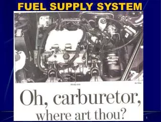
FUEL SUPPLY SYSTEMS
FUEL SUPPLY SYSTEMS. The fuel passes through a number of stages before reaching the combustion chamber. It includes the filtration and atomization of fuel into fine particles.

FUEL SUPPLY SYSTEMS
E N D
Presentation Transcript
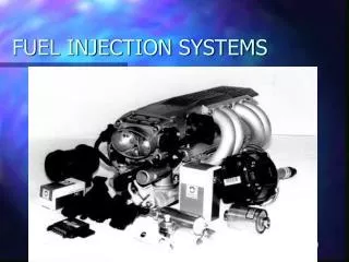
FUEL SUPPLY SYSTEMS • The fuel passes through a number of stages before reaching the combustion chamber. • It includes the filtration and atomization of fuel into fine particles. • It is necessary to atomize the fuel before entering into the combustion chamber so that complete combustion of fuel can take place. • There are different fuel supply systems for spark ignition (petrol) and compression ignition (diesel) engine.
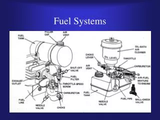
In petrol engine the combustible mixture of fuel is prepared outside the combustion chamber. • Proper air-fuel ratio is maintained with the help of a device known as carburetor and this mixture is inducted into the combustion chamber. • The air fuel ratio depends upon the various conditions. The engine needs a richer mixture while starting and leaner mixture at normal running conditions. • Such conditions must be fulfilled before entering the combustion chamber. • The fuel from the tank is delivered to the float chamber attached to the carburetor with the help of fuel pump. • The fuel pump maintains the constant pressure. In carburetor fuel is mixed with air in required proportion. • After that the mixture of fuel and air is inducted into the combustion chamber.
In diesel engine only air is injected during the suction stroke and it is compressed during compression stroke. • Fuel is injected into the combustion chamber in the form of fine spray at the end of compression stroke. • A fuel injection system in a diesel engine has to satisfy the following requirements: 1. To inject the fuel at the right time in the cycle. 2. The fuel should be properly atomized. 3. The correct quantity of fuel should be injected depending upon the load.
Fuel pump takes the fuel from fuel tank and delivers it to the fuel filter. • When the pressure is developed in the injection pump the fuel flows from injection pump to the fuel injector under pressure. • The fuel injector is either a single hole nozzle or multi-hole nozzle.
Under normal conditions it is desirable to run the engine on the maximum economy mixture, viz., around 16:1 air-fuel ratio. • For quick acceleration and for maximum power, rich mixture viz., 12:1 air-fuel ratio is required.
An SI engine works with the Air-fuel mixture ranging from 8:1 to 18.5:1. But the Ideal ratio would be one that provides both maximum power and best economy, while producing the least emissions. • But such a ratio does not exist because fuel requirements of an engine vary widely depending upon temperature, load, and speed conditions . • For complete combustion , thorough mixing of fuel in excess air is needed. • Lean mixtures are needed for best economy and rich mixtures are needed to supress combustion knock. • A rich mixture is required for High load and high speed and idling conditions. • Best economy is expected at part throttle. • A carburettor should supply the mixture ratio according to the engine requirements
CARBURETTOR • Carburettor is the device that mixes petrol and air in correct propotions and supplies to the combustion chamber in right quantity. • A Carburettoratomises, vaporises and mixes the petrol in correct propotions with air as required by the engine and supplies the right quantity of the mixture to the engine.
AIR CLEANER CHOKE VENTURI Float Valve Float Arm Float Chamber Float THROTTLE VALVE
VenturiPrinciple The pressure at "1" is higher than at "2" because the fluid speed at "1" is lower than at "2".
Construction and Working of Simple Carburettor • Simple carburettor consist of a venturi and a fuel jet. • For maintaining the level of fuel in the jet, a float chamber is usually required. • A throttle valve in the form of a flat circular metal disc mounted on spindle is provided for controlling the flow of air-fuel mixture to the induction manifold. A rotary type valve also can be used instead of disc type.
The level of fuel is just kept slightly below the top of the jet to prevent the leakage when not in operation. • Usually 1.5 mm difference is kept between the top of the jet and the surface of the fuel in float chamber. • A needle valve controls the passage of fuel from the fuel pump, when the air begins to flow past the jet, a low pressure zone is created in the venturi because of the increased velocity of air.
The fuel begins to rise because of the difference in the air pressure on the fuel which is equal to the pressure of the atmosphere and on the fuel in the jet at the venturi and issue out from the jet in the form of fine spray. A minute petrol particles present a large surface area being exposed to the air stream. The fuel is not completely vaporized in carburettor and some globules of fuel still enter the induction manifold and are vaporized during the compression stroke in engine cylinder. A choke valve controls the flow of air into the carburettor. A gas tight connection is provided between the carburettor and the induction manifold. • When two concentric venturies are provided, the discharge end of the inner venturi called "Primary Venturi", which lies just at the throat of the main venturi. A higher velocity of air which aids in the atomization of the fuel, is obtained at the throat of primary venturi due to lower pressure comparing to main venturi.
DEFECTS IN THE SIMPLE CARBURETTOR • The simple carburettor, would work well if the engine is running at one particular speed and load. • The nozzle and the venturi sizes then can be set once and the carburettor will then work satisfactorily at that particular speed and load. • But in actual practice, the engine has to run at different speeds and loads ranging from the lowest to the highest therefore certain irregularities creep in the functioning of this simple carburettor.
The two basic reasons for defects are: 1.If the carburettor is designed to work at high speeds at full throttle, it will not work at low speeds and part throttle, reason being that in the later case the suction created at the venturi will not be sufficient to draw fuel from the nozzle. 2. The coefficients of discharge for air and fuel vary in different amounts with the change of depression. Whereas the coefficient of discharge for air becomes almost constant at certain value of depression, the coefficient for fuel increases gradually. Therefore, if the carburettor is set at one particular speed, it will give richer mixture at higher speeds and leaner mixture at lower speeds.
Starting difficulty For starting, it is seen that very rich mixture is required, but actually the mixture provided by the simple carburettor will be very lean. The different methods to provide for enrichment of fuel at very low speeds are :(a) Ticklers: These are devices used to cause flooding of carburettor at the start. (b) Choke: This is a simple butterfly valve fitted at the top of air horn. For starting, choke is closed so that very small amount of air gets past it and the throttle valve is open which delivers sufficient fuel to provide a mixture rich in quality, though small in quantity.
CHOKE WITH STRANGLER VALVE ECCENTRIC CHOKE TICKLERS
(C)Adjustable Area Jet: A long tapered needle is used which is screwed into the jet as shown in the figure. For starting the screw is loosened so that the jet area providing fuel is increased and thus rich mixture is provided for the start.
The choke valve must be opened immediately when the engine starts. This is achievedby any of the following methods: by mounting the choke eccentrically. With this, when the engine starts, the forces due to pressure on the two sides of the choke spindle are unequal, their difference producing a turning moment to open the choke.(ii) by the use of strangler valve fitted on the choke. As soon as the engine is started, the air pressure forces open the strangler against the spring pressure and the air enters the carburettor avoiding the mixture being over-rich. By this time the driver also presses the choke knob to open the choke valve. An automatic choke employed in modern automobiles.
Idling Difficulty • During idling suction at the main nozzle is insufficient to draw fuel from the chamber since throttle is closed. • Therefore a separate supply circuit of fuel must be provided on the engine side of the throttle valve during idling. • This is done by providing a separate idle jet and an air bleed hole, so that metered quantities of air and fuel are drawn into the idle passage where they form an emulsion. • The volume of the mixture and hence the idle speed are controlled by the idle adjustment screw.
Operation at different speeds • A simple carburettor provides richer mixture at high speeds and leaner mixture at low speeds. • The process of adjusting the mixture strength at all the speeds so that thought the whole range correct proportions of air fuel mixture are maintained is compensated. Various devices used for providing compensation are • Extra air valve • Compensating jet • Air bleed compensation • Multiple jet compensation • Suction controlled devices
Extra Air valve • This is a spring loaded valve arranged to open by means of engine suction as shown in the figure. It is thus controlled by the spring stiffness and engine suction
Air bleed compensation A-A: no load C -holes communicating the air bleed holes to atmosphere B-jet tube having air bleed holes
As the throttle is opened gradually, due to depression at the venture, the fuel in the tube and the nozzle around is consumed, providing gradually richer mixture. • Simultaneously, the level of fuel in the jet tube and nozzle drops uppermost holes in the jet tube to put them in direct communication with atmosphere through holes C. • This destroys the depression to some extent and the fuel flow thus decreases. • More and more demand for fuel increases more fuel is consumed and more holes will communicate with the atmosphere thus compensating for the richness of the mixture at larger depression.
As the depression increases throttle is opened more and more and cap E is lifted progressively and jets open to air one by one. • First jet is open more and it supplies more fuel compared to second nozzle thus compensating the mixture . Suction controlled devices: Here engine suction is used to actuate a needle which decreases the effective nozzle area as speed is increased, thus providing compensation
Difficulty at high speeds High speeds Low speeds • Weak air-fuel mixtures supplied by the single jet carburettorwill not give enough power at High speeds. • A metering rod with stepped diameter end in the main jet is used for this purpose. • At high speeds metering rod is pulled up so that small dia meter part is in the well supplying more fuel
Acceleration Difficulty When sudden acceleration is required, the throttle is opened suddenly. This causes the maximum amount of air to come at once but the fuel supply lags there by causing ‘engine stumble’ or ‘ hesitation’ which is due to weak mixture To avoid this a separate pump which provides fuel momentarily till the rich mixture is delivered is used. when the accelerator pedal is pressed , the outlet valve is opened and the fuel is forced out of the acceleration jet. When the pedal is released, piston moves up there by sucking the fuel from the float chamber. Thus pump is ready for the next discharge
Influence of Weather As already explained simple carburettor can be set to deliver correct air fuel mixture only at perticular speed. If a carburettor is set for a perticular weather for instance Summer ,during winter it supplies weak mixture because density of air increases more compared to fuel. Similarly carburettor set for winter will give rich mixture during summer. In modern carburettor climatic control devices are provided. These control the mixture strength by varying either fuel jet area or air intake.
At higher altitudes , the air density decreases due to fall in pressure eventhough temperature decreases. This makes the carburettor to deliver rich mixtures at higher altitudes. To overcome this an arrangement is shown in the figure. Two pipes AB and CD connect the top of the float chamber to the air horn. S is a valve in the pipe CD. For ordinary low altitudes S is closed and thus the fuel in the float chamber is under atmospheric pressure because of pipe AB. As the altitude is increases valve S is opened gradually and by doing so engine suction is applied to the float chamber, thus decreasing the pressure here which decreases the fuel supply making the mixture weak.
Icing Trouble As the fuel is atomised and evaporated in the carburettor, it causes cooling of sorrounding areas . In localities which are cold , there is thus always the danger of ice formation and choking of venturi tube. Some methods used to prevent ice formation are • By heating the carburettor idle ports and throttle valve area by means of the engine exhaust. • By providing engine hot water passes around the carburettor.
Types of Carburettor Depending on the choke area carburettors are classified As: 1.Open Choke or constant choke carburettor 2.Variable Choke or Constant depression carburettor Carburettors are also classified as a) Up-drought b)Horizantal c) Down-drought Carburettors.
Constant Choke Carburettor • Here the main orifice known as the choke tube or venturi is of fixed dimensions and metering is affected by varying the pressure drop across it e.g • Zenith carburettor • Solexcarburettor • Carter carburettor • Stromberg carburettor
Working of SolexCarburettor • Normal running • Solexcarburettor consist of a conventional float(1) in a float chamber • The fuel is provided through the main metering jet(2) and the Air by the choke tube or Venturi(3) • The fuel from main jet passes into the well of air bleed emulsion system; (4) is the emulsion tube which has lateral holes. • Air correction jet (5),calibrates the air entering through it and ensures automatically the correct balance of air and fuel. • The metered emulsion of fuel and air is discharged through spraying orifice or nozzle(6) drilled horizantally in the vertical stand pipe in the middle of the chock tube • (7) is the conventional butterfly valve.
2. Cold starting and warming: The provision of a Bi-starter or progressive starter is the Unique feature of solexcarburettor. • starter valve is in the form of a flat disc(8) with holes of different sizes • These holes connect the starter petrol jet (9) and starter air jet sides to the passage which opens into a hole just below the throttle valve at (11). Either bigger or smaller holes come opposite to the passage depending upon the position of the starter lever(12).The starter lever is operated by flexible cable from dash board control • For starting the lever 12 is fully pulled out and bigger holes are in contact and throttle is closed and the entire suction is applied is applied to passage 11 sucking petrol from jet 9 and air from jet 10. • Just after starting for some time both starter jet and main jet are supplying the fuel and intermediate holes are in contact with throttle open partially • When the engine reaches the normal running temperature starter is brought to ‘off’ position
3. Idling and slow running: • From the lower part of the well of the emulsion system a hole leads off to pilot jet(13) • At idling throttle partly closed and engine suction is applied at pilot jet. Fuel from the pilot jet mixes with small amount of air from the small pilot air bleed orifice(14) • The rich mixture for idling is discharged into the throttle body past the idling control screw(15). • By-pass orifice(17) provided on the venturi side of the throttle valve ensures smooth transfer of idle and low speed circuit to the main jet circuit .
4.Acceleration: • A diaphragm type acceleration pump supplies spurt of extra fuel needed for acceleration through pump injector(18) • Pump lever (19) is connected to the accelerator so that pressing the pedal, the lever moves towards the left, pressing the membrane towards the left, thus forcing the petrol through pump jet (20) and injector(18). • On making the pedal free, the lever moves the diaphragm back towards right creating vaccum towards left which opens the pump inlet valve(21) and thus admits the petrol from the chamber into pump.
Constant Depression Carburettor • SU CARBURETTOR SU Carburetters (named for Skinners Union, the company that produced them) were a brand of carburettor usually of the side draught type but down draught variants were also used