Download

1 / 33
330 likes | 469 Views
Design of Hirbawi Center Prepared By : Juman Abu zaid Haneen kharraz Israa Abu Galuen. Design of Hirbawi Center By: Juman Abu zaid Haneen kharraz Israa Abu Galuen. Chapters. Chapter One : Introduction Chapter Two : Preliminary Design

E N D
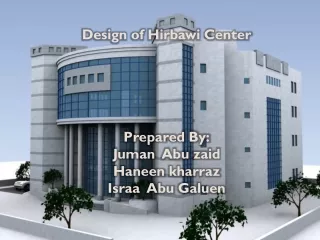
Design of Hirbawi Center Prepared By: Juman Abu zaid Haneenkharraz Israa Abu Galuen Design of Hirbawi Center By: Juman Abu zaid Haneenkharraz Israa Abu Galuen
Chapters Chapter One : Introduction Chapter Two : Preliminary Design Chapter Three : 3 Dimensional Structural Analysis and Design
Chapter One :Introduction Project title : Hirbawi Center A building lies in the east side of Tulkarm, this building consists of five stories of (5372 m2) Under ground floor consists of Car Parking & water tank and it’s height 3.8 m Ground Floor (Entrance Level) :Retail – Commercial and Small Offices it’s height 4.9 m 1st floor consists of commercial and Small Offices it’s height 4.3 m 2nd & 3rd floor consists of apartments, Offices and Maintenance area for elevators, solar panels for water heating, it’s height 3.6 m
Design Data Yielding strength of steel, fy = 4200 kg/cm2. B300 → fc = 240 kg /cm2 → Ec = 2.34×10ˆ5 Kg /cm2 Unit weights of materials: Reinforced concrete = 2.5 ton/m3 . Blocks = 1.2 ton/m3 . Stone =2.6 ton/m3. Sand =2 ton/m3. soil bearing capacity = 4 kg/cm2 .
Design Data code used in the design is ACI 2008 (American Concrete Institute . Program used SAP 2000 V14 (structural analysis program). Methods: Ultimate design method
Loads &Load combinations : Load combinations 1.4D 1.2 D + 1.6 L + 0.5 S. 1.2 D + 1.6 S + 0.5 L 1.2 D + 1.6 W + 0.5 L + 0.5 S 1.2 D ± 1.0 E + 0.5 L + 0.2 S 0.9 D ± ( 1.6 W or 1.0 E ) Where : D : Dead Load L : Live Load W : wind Load S : snow load E : Earthquake load
Design loads: live load is 500 kg/m2. Super imposed dead load is 400 kg/m2 . The earthquake load is response spectrum in x and y directions, Ca = 0.18, Cv= 0.25
Chapter Two: Preliminary Design Slab section: For flat plate slab Min t =Ln/33 t slab =28.2 cm ….use t= 30 cm.
Analysis and design frame using Sap The flat plate can be divided to frames in each direction . Here , calculations are made for frame 1 shown in figure ( 1-1) Results from sap : Frame bending moment as shown in figure (1-2)
Negative moment at exterior support=0.75Mo Positive moment =0.6Mo Figure ( 1-4 ) column strip moment Figure (1-5) column strip steel reinforcement
For middle strip Negative moment at exterior support = 0.25 Mo Positive moment = 0.4 Mo Figure (1-6) middle strip moment Figure (1-7) middle strip steel reinforcement
Chapter Three: Three Dimensional Structural Analysis and Design Figure (1-8) 3-D model
Structural modal verification • Check of compatibility • Compatibility is achieved as the structure behaves as a one unit as in reality through the meshing of all areas and dividing of all frames such as beams and columns in a way that the point of divisions meet. Compatibility was achieved as shown on figure (1-9)
Check of equilibrium Live load manually= 2685.69 ton Total dead load manually= 9100.39 ton Results of live and dead loads from SAP • % of error for dead load = 0.49 % < 5 % • % of error for live load= 0.58 % < 5 %
Stress strain relationships: verify the magnitude of moment which extracted from SAP & manually: Result manually Mu = 88.02 • Result from SAP • Mu = 81.7 Figure (1-9) frame bending moment manually % of error = 7.7 % Figure (1-10) frame bending moment from sap
Check Building Natural Period From sap analysis result ( 0.4707) Ta = 0.1 * N = 0.1 * 5 = 0.5 so ( 0.4707) from sap analysis result Ok (approximate compassion
Column design Columns classification: Short columns Long columns If it is short if the following achieved: For braced columns : KL/r≤ 34-12(M1b/M2b). For unbraced columns : KL/r≤ 12
Column design The design load can be calculated using the following equation: Pd= 𝜙Pn=𝜙*λ {0.85* f´c(Ag-As) + As*fy} 𝜙 = 0.65 for tied columns 𝜙 = 0.75 for spiral columns λ = 0.8 for tied columns λ = 0.85 for spiral columns
Slab design Design requirements: Bending moment resistance: = Asmin =ρ shrinkage*b*d
Slab design • For frame 1 refer to figure ( 1-1 ) . Figure (1-11) Bending moment for column strip for frame 1 in slab1 X-dir Figure (1-12) column strip reinforcement for frame 1 in slab1 X-dir
For middle strip : Figure (1-13) Bending moment for middle strip for frame 1 in slab1 X-dir Figure (1-14) Middle strip reinforcement for frame 1 in slab1 X-dir
Footing Design The function of foundation is transmitting load of structure to soil layers. The soil in this project is rock . The ultimate bearing capacity of a soil supporting the footing is 4 kg/cm2.
Types of footing in this project Wall footing: to support bearing wall Single footing (continues): to support columns .
Wall footing design • After calculations : • width of wall = 1.7 m • Depth = 0.4 m Figure (1-15) wall footing
Maximum area of steel from sap ( footing ) = 11.33 cm² Use 1 Ø 16 / 15 cm . • Maximum area of steel from sap ( Wall ) = 7.86 cm² • Use 1 Ø 16 / 25 cm
Design of stairs : Concrete compressive strength, f'c= 240kg/cm2. Yield Strength of steel, fy=4200kg/cm2. The thickness of stairs slab is = 0.15m Loads For landing part, S.I.D=0.3 ton/m2 For flight part, S.I.D = 0.3 ton/m2 Live load=0.5 ton/m2 .
Steel of beam use 5 𝜙 16 bottom bars and 5 𝜙 12 top bars Figure (1-16)stairs plan Steel of the flight use (1 𝜙 14 / 15cm ) main steel
Use (1 𝜙 12 / 30 cm ) secondary steel Steel for landing : Use (1 𝜙 18 / 10 cm ) main steel Design of water tank Steel for Base of tank Use (1ф20/25 cm ) as bottom steel. 1ф20/10 cm ) as top steel.) Use Steel for (curve) Use(1ф14/20 cm ) as bottom steel. Use(1ф14/20 cm ) as top steel.
Thank you تم بحمد الله