Download
1 / 16
260 likes | 556 Views
This article delves into the essential components of Nano/Microelectromechanical Systems (N/MEMS) used for measurement and information processing. It covers the role of measurands, sensors, preprocessors, and actuators, explaining their functions and classifications. The characteristics of ideal transducers, including self-exciting and modulating types, are explored, along with their input-output relationships. Additionally, it discusses the performance parameters and potential issues in transducers, such as non-linearity, noise, and hysteresis, providing valuable insights for system control in open-loop and closed-loop processes.

E N D
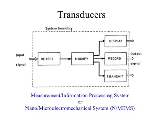
Transducers Measurement/Information Processing System or Nano/Microelectromechanical System (N/MEMS)
N/MEMS: Basic Components • Measurand: input signal which is the physical or chemical quantity to be measured. • Sensor (input transducer): it is a device that converts a non-electrical physical or chemical quantity into an electrical signal. Sensor detects the measurand. • Preprocessor/processor: is a device(s) that modifies the signal from the sensor without changing the form of energy that describes the signal. • Actuator (output transducer): is a device that converts an electrical signal into a physical or chemical quantity.
Ideal Transducer Characteristics • Definitions • Self-exciting transducer: is one which does not need an external poser supply to work (e. g., thermocouple). • Modulating transducer: is one which needs an external modulating source (e. g., photodiode is a radiant sensor whose forward current is modulated by photo-induced electrons) • A transducer may be regarded as a system with an input x(t) and output y(t). • In case of a modulating transducer xo(t) is the external supply signal which should ideally be stationary and noise free. yo(t) is zero-signal output.
Self-exciting: Modulating: Ideal input-output relationships for linear transducers
Non-Ideal Linear Transducer Characteristics • In general for a time-dependent linear transducer we have: • For a first order case: • Where for a self-exciting transducer y(t)=0 and x(t)=0 at all t, and y(t)=yo(t) at x(t)=0 for all to for a modulating transducer. ao relates to the transducer gain, and a1 relates to its characteristic time response. (a)
In the case of instantaneous change in the measurand from zero to xo: i. e., a step change in input signal: • Taking the Laplace transform of both sides of (a) y(0) is zero for a self exciting transducer and is yo for a modulating transducer. • The transfer function for self-exciting transducer G(s)=Y(s)/X(s) is • 1/ao= Gain and t=a1/aois the characteristic response time.
The output of the transducer Y(s) in Laplace space to the step input of height xo is • Taking the inverse Laplace transform, one obtains for self-exciting transducer • For a modulating transducer we have;
Important Parameters Response: Gain (A): Sensitivity Band-width 1/t Baseline Signal (yb) is y(t) at x(t)=0
Undesirable Transducer Characteristics • Non-linearity: response not proportional to input signal. • Slow response: output is slow to reach a steady state value. • Small working range: operating range is narrow. • Low sensitivity: can only respond to high input signal. • Sensitivity and baseline drifts: output varies with time. • Aging: output varies with age. • Noise: output contains unwanted random signal. • Hysteresis: non-reproducible readings.
Input-sensitivity relationship for ideal and real transducers
System Control: Open-Loop Process • Xin(s) = input signal to system • Ys(s) = Gs(s)Xin(s) = sensor’s output • Yp(s) = Gp(s)Ys(s) = processor’s output • Ya(s) = Ga(s)Yp(s) = actuator’s output = system output = Yout • Gs, Gp, and Ga are sensor’s, processor’s, and actuator’s transfer functions, respectively. • Overall • Go(s) = Gs(s)Gp(s)Ga(s), which is system’s transfer function, Yout(s) = Go(s)Xin(s)
System Control: Closed-Loop Process • The overall transfer function Gc(s): • H(s) is the transfer function for the control sensor