Download
1 / 7
70 likes | 96 Views
Updates on modifications to the HBD gas system at Brookhaven National Laboratory to enhance flow to detectors without compromising gas quality, including changes in the Monitoring Hut and gas rack to optimize flow path and reduce pressure.

E N D
Update on the HBD Gas System Modifications Robert Pisani Brookhaven National Laboratory
Update on the HBD gas system The main goal is to increase flow to the two detector as much as possible without compromising gas quality. In addition, funds for this had to be found since it was not in the original budget. • Three places changes can be made • The Monitoring Hut • The rack in the mixing house • The small bypass panel in the IR (this probably will not do much)
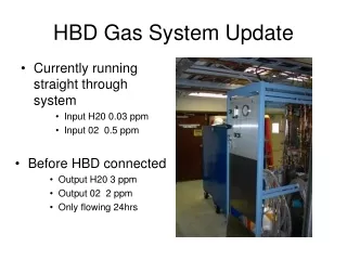
Jobs in the Hut • Modify Flow path to gas analyzers. (DONE) • Reduce restrictions by replacing flowmeters and valves (DONE) • Install gauge and new valve to make switching from vacuum in the monitor to gas a little easier. (DONE) • Replace H20 sensors with ones that work. I haven’t received the OK to orders these yet. (Around $9k)
Analyzer source moved Old Setup Source where HBD analyzer gas was being taped into was changed. The old setup (above) had 10-20% of the HBD return gas diverted to the analyzers and returned after the monitor (parallel system). I was asked to have all the gas first enter the Monitor and then pass it through the analyzers as in the original drawing. -DONE New Setup
Old Flowmeter New picture of the Hut Old Flowmeter with built-in valve replaced with low impedance flow indicator to help reduce the pressure needed to feed the input analyzers. Old Flowmeters with built-in valves were replaced with low impedance flow indicator and separate higher Cv bellows valve ¼” turn Argon valve that feeds the monitor was replace with multi-turn bellows valve. Vac-1Atm pressure gauge was installed to help bring the system to atm after pumping. Choke valves to force flow to analyzers were here New choke valve and tap location. ¼” lines to analyzers replaced with ½” flex lines to help reduce pressure. Replace ¼” hard pipe feeding Ar to monitor with flex line
HBD Gas RackWork I will do in the next few weeks Solenoid valve to the vent had to be changed to accommodate much higher flow rate than designed (10x higher). Custom valve ordered and in hand Pressure transmitter may need to be replaced. This was at upper reading limit in Run6. With the new flowmeters, the higher pressures in the rack may not be needed Old flowmeter with built-in valves needs to be replaced with low impedance flow indicator and separate valve. This valve controls how much gas passes through the purifiers. Right now all gas pass though it. This flowmeter was already replaced once mid-Run6 to increase flow to the HBD Old flowmeter without built-in valves needs to be replaced with low impedance flow indicator. This indicates how much total gas is going to the system. This flowmeter was already replaced once mid-Run6 to increase flow to the HBD. It need to be replace again for the higher flowrate. Replace Purifier to handle the higher gas flow--DONE
Summery • With the changes to the hut alone, I have been able to increase the flow by a factor of 2 over what was delivered in Run6 ( to about 7 lpm to each arm) while dropping the input pressure by a factor of 10 (30”W.C. to 3”W.C.) This was in straight trough. This is with ½” pipe instead of the HBD in the IR and with the compressor off. • The changes to the rack should help a little more. Pushing the gas to the detector should be OK. The problem may be pressure buildup in the return lines caused by both the size of the SS pipes and the fact that we choke the lines to feed the analyzers. What pressure can we safely run the detector? Right now the bubbler limit is 0.5”W.C or 1.25 mbar. Last year we ran very close to this limit. • May also look into changing the bypass valves located on a panel below the HBD. This is expensive and my not help much since the detector may be our next restriction with its 3-way ¼” valves.